Full function initiator with integrated planar switch

Active Publication Date: 2007-11-15
REYNOLDS SYST
View PDF17 Cites 11 Cited by
  • Summary
  • Abstract
  • Description
  • Claims
  • Application Information

AI Technical Summary

Problems solved by technology

Heretofore, it was not desirable to manufacture a detonator with an exploding foil initiator that was operable in all three modes of operation as the added functionality included a commensurate increase in the size and weight of the detonator.
Size and weight are important characteristics as it is often times desirable that the device in which the detonator is employed be as small in size and light in weight as possible.
Complic

Method used


Image

  • Full function initiator with integrated planar switch
  • Full function initiator with integrated planar switch
  • Full function initiator with integrated planar switch

Examples


Embodiment Construction

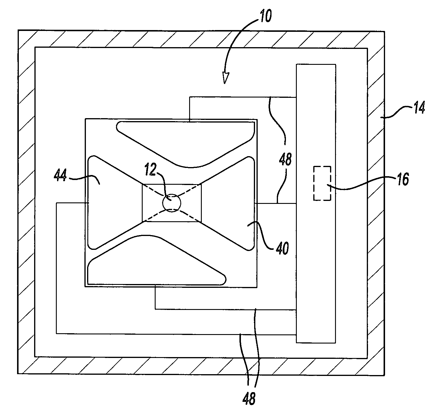
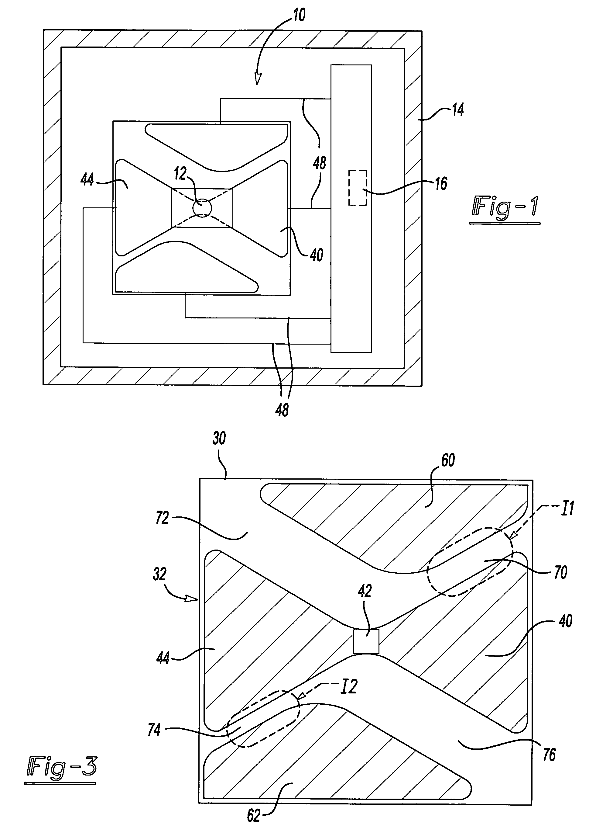
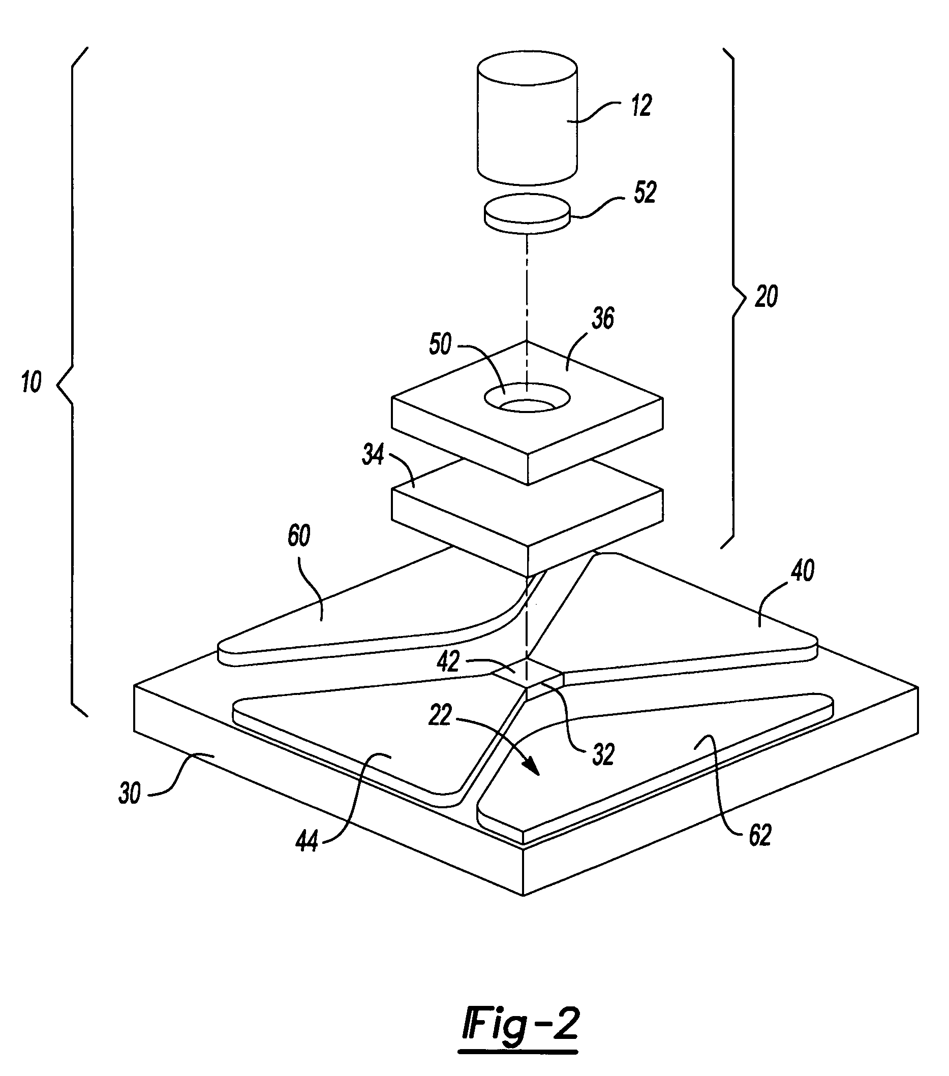
[0019] With reference to FIGS. 1 and 2 of the drawings, a detonator constructed in accordance with the teachings of the present disclosure is generally indicated by reference numeral 10. The detonator 10 is employed to initiate a detonation event in an explosive charge 12. The explosive charge 12 can be a secondary explosive material, such as pentaerythritol tetranitrate (PETN), cyclotrimethylenetrinitramine (RDX), trinitrotoluene (TNT) or hexanitro stilbene (HNS), but may alternatively can be a primary explosive, such as mercury fulminate, lead styphnate or lead azide. The detonator 10 can be disposed in a sealed housing 14 and can be operatively associated with a source of electrical energy 16 as will be discussed in greater detail, below. The housing 14 can be sealed, for example with a hermetic seal, so that both the detonator 10 and the explosive charge 12 are impervious to moisture, dirt, contaminants or changes in atmospheric pressure or composition, which may detrimentally e...


PUM


Abstract

A switch device having a base, a first electrically conductive pad coupled to the base, a second electrically conductive pad coupled to the base, a first electrically conductive projection and a second electrically conductive projection. The second electrically conductive pad is spaced apart from the first electrically conductive pad by a first predetermined distance. The first electrically conductive projection is coupled to the first electrically conductive pad and extends into the first gap. The second electrically conductive projection is coupled to the second electrically conductive pad and extends into the first gap. The second electrically conductive projection is spaced apart from the first electrically conductive projection by a second predetermined distance. The first and second electrically conductive projections form an electrical interface.

Description

CROSS-REFERENCE TO RELATED APPLICATIONS [0001] Other aspects of the present disclosure are claimed in co-pending U.S. patent application Ser. No. 11 / ______, filed on even date herewith entitled “Full Function Initiator With Integrated Planar Switch”.INTRODUCTION [0002] The present disclosure generally relates to detonators and initiation firesets for initiating a detonation event in an explosive charge and more particularly to a detonator with an exploding foil initiator having multiple triggering mode functionality. [0003] Exploding foil initiators, which are also known as slappers, are employed to generate a shock wave to initiate a detonation event in an explosive charge. In a conventionally designed exploding foil initiator, a bridge is connected to a power source through two relatively wide conductive lands or pads. In a system wherein operation of the exploding foil initiator is initiated by an external trigger (i.e., standard mode operation), the power source can typically be...

Claims


Application Information

Patent Timeline
IPC IPC(8): F42C19/12
CPCF42B3/10
Inventor NANCE, CHRISTOPHER J.
Owner REYNOLDS SYST
Why Eureka
Try Eureka