Coating Apparatus

a technology of coating apparatus and spray nozzle, which is applied in the direction of coatings, movable spraying apparatus, confectionery, etc., can solve the problems of poor operability, complicated configuration of the apparatus, and difficult layout of the apparatus, so as to improve the sliding property and simplify the apparatus. , the effect of improving the efficiency of the operation of installing or exchanging the spray nozzle uni

Inactive Publication Date: 2007-11-15
POWREX
View PDF8 Cites 11 Cited by
  • Summary
  • Abstract
  • Description
  • Claims
  • Application Information

AI Technical Summary

Benefits of technology

[0016] Still further, with the above construction, the coating apparatus further includes a discharging mechanism for discharging particle products which have undergone coating treatment from an inside of the rotary drum, and at least a partial surface of a discharging path of the particle products may be formed of a surface with unevenness for improving a sliding property.
[0017] At a time of installing or exchanging the spray nozzle, the spray nozzle unit can be pulled out from the rotary drum by a swing operation of a swing arm, so operations of installing or exchanging the spray nozzle unit can be performed efficiently.
[0018] It is not necessary to provide a complicated mechanism such as a conventional slide mechanism, thereby making it possible to obtain a simple configuration of the apparatus. Further, since the spray nozzle unit can be moved by a swing operation, compared with a conventional configuration in which the spray nozzle unit is moved by a operation in an axial direction, a space to be kept on a front side of the rotary drum may be smaller, which is advantageous in terms of the layout of the apparatus.
[0019] By attaching the liquid tube holder to the swing arm removably, the spray nozzle unit, the liquid tube of a spray solution, and the liquid tube holder can be attached / detached with respect to the swing arm as one cassette in such a state that they are assembled. Therefore, the operations of installing or exchanging the spray nozzle unit can be performed more efficiently.
[0020] By inserting the air tube of compressed air connected to the spray nozzle unit into the swing arm, a portion where the air tube is exposed to inside and outside of the apparatus is reduced, thereby making it possible to improve the appearance of the entire apparatus.
[0021] By forming at least a partial surface of the discharging path of particle products, of the surface provided with unevenness for improving a sliding property, particle products do not remain during discharge, thereby making it possible to perform efficient discharging.

Problems solved by technology

First, regarding the arrangement of the spray nozzle, in JP 2003-1083 A and JP 07-328408 A, the spray nozzle is attached to the nozzle support member placed inside the rotary drum in a fixed manner, so it is necessary to perform an attachment / detachment operation by inserting hands in the rotary drum at a time of installing or exchanging the spray nozzle, which results in poor operability.
In this case, although the operability is better than that as disclosed in JP 2003-1083 A and JP 07-328408 A, it is necessary to provide the slide mechanism separately, thereby making the configuration of the apparatus be complicated.
Furthermore, since the nozzle support member is moved in the axial direction to be pulled out from the rotary drum, a relatively large space is required on a front side of the rotary drum, which may make the layout of the apparatus difficult.
Next, regarding the discharge of particle products, in the discharging mechanism as disclosed in JP 2004-97853 A and JP 2726062 B, the particle products remain in a discharging path, depending upon the shape, property, a discharge amount per unit time, and other conditions of the particle products, with the result that efficient discharge may not be performed.

Method used


Image

  • Coating Apparatus
  • Coating Apparatus
  • Coating Apparatus

Examples


Embodiment Construction

[0037] Hereinafter, an embodiment of the present invention will be described with reference to the drawings.

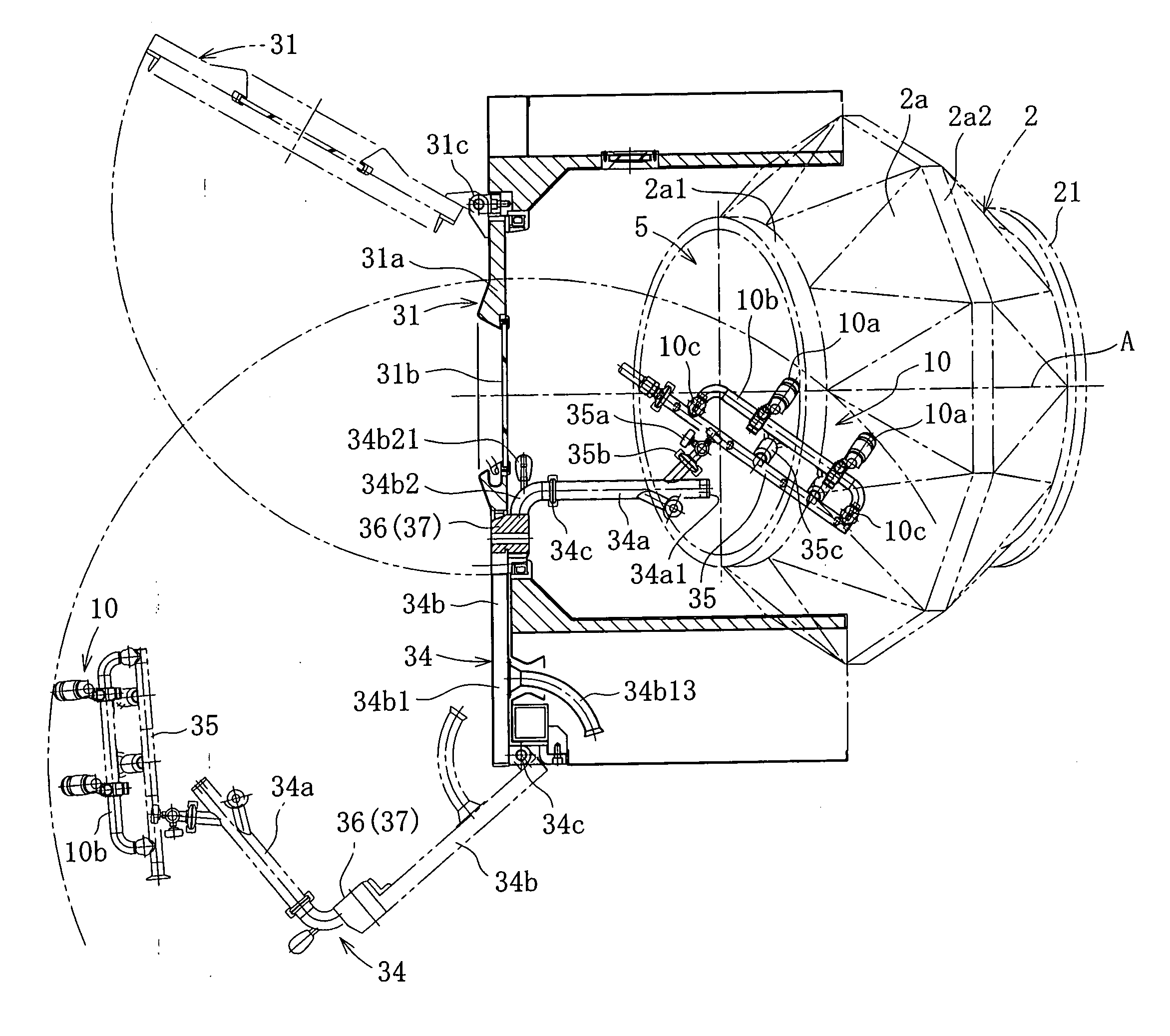
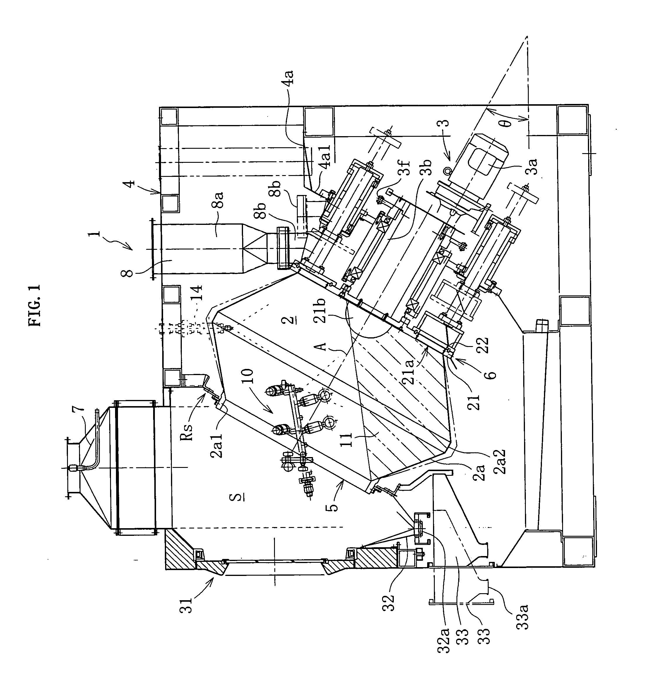
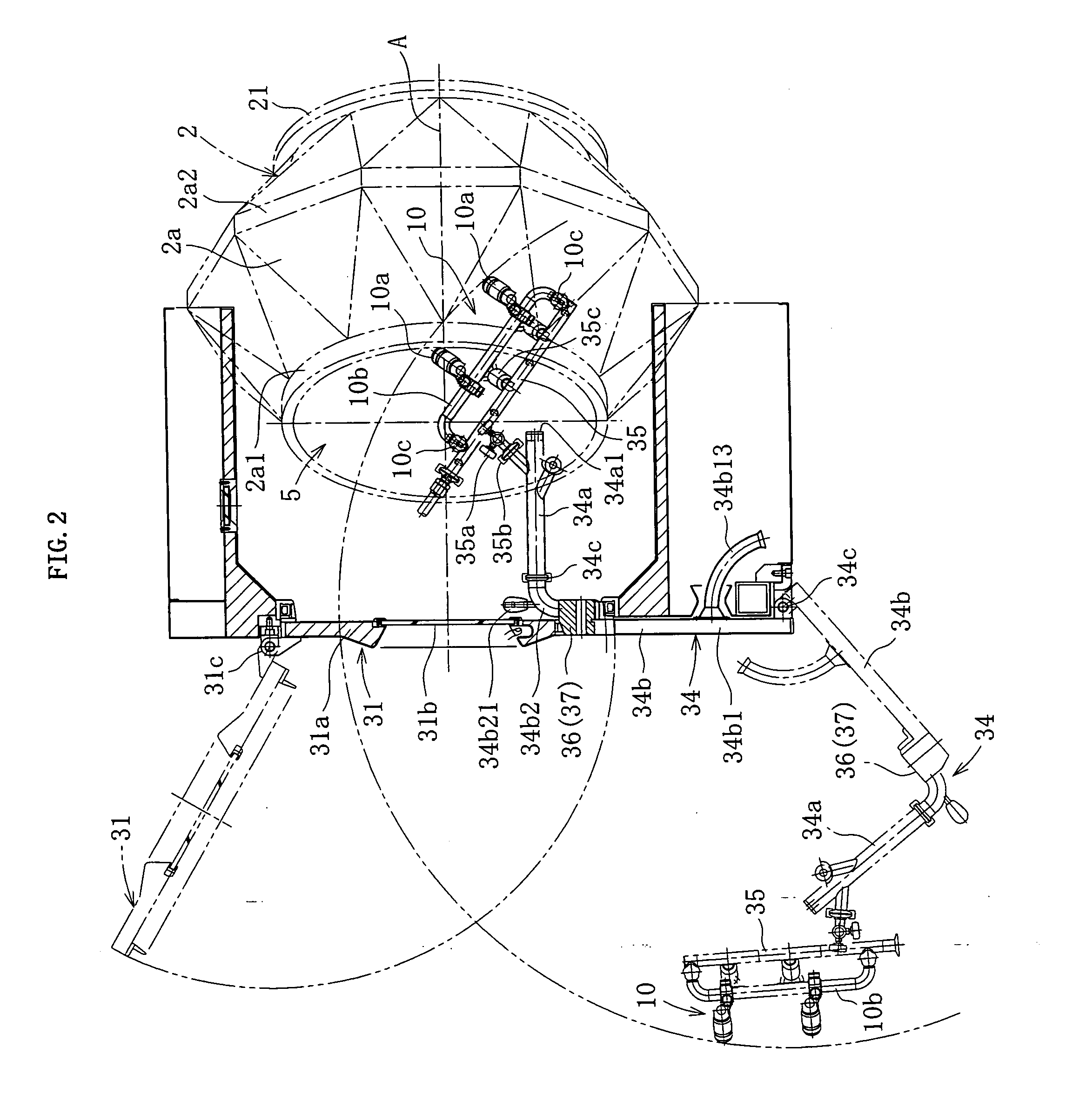
[0038]FIG. 1 shows a coating apparatus 1 according to this embodiment. The coating apparatus 1 includes a rotary drum 2 placed rotatably around an axis A inclined by a predetermined angle θ (e.g., θ=30°) with respect to a horizontal line, and a rotation driving mechanism 3 for rotating the rotary drum 2 in a forward direction and / or a backward direction, and the rotary drum 2 and the rotation driving mechanism 3 are accommodated in a casing 4 formed of a stainless steel plate or the like.

[0039] The rotation driving mechanism 3 is configured so as to input a torque of, for example, a driving motor 3a with a speed reducer to a hollow driving axis 3b connected to a back end (end on an inclination lower side) of the rotary drum 2 through a chain (not shown) and a sprocket 3f. In this case, the rotary drum 2 as well as the driving axis 3b are supported rotatably on an inclined wa...


PUM


Abstract

Provided is a coating apparatus, which has satisfactory operability at a time of installing or exchanging a spray nozzle, is not complicated in structure, and is advantageous in terms of layout. A rotary drum (2) is rotated around an axis (A) inclined with respect to a horizontal line, and has an opening (5) at one end on an inclination upper side. A spray nozzle unit (10) is removably attached to a swing arm (34), and the swing arm (34) can swing with respect to a swing axis (34c). Owing to the swing operation of the swing arm (34), the swing nozzle unit (10) can be moved between the inside and the outside of the rotary drum (2).

Description

BACKGROUND OF THE INVENTION [0001] 1. Field of the Invention [0002] The present invention relates to a coating apparatus for performing coating, mixing, drying, etc. of particles of a drug, food, agricultural chemicals, etc., and more particularly to a coating apparatus with a rotary drum that is rotated around an axis. [0003] 2. Description of the Related Art [0004] In order to provide a film coating, a sugar coating, or the like to a tablet, a soft capsule, a pellet, a granule, and the like (hereinafter, collectively referred to as “particles”) of a drug, food, agricultural chemicals, etc., a coating apparatus with a rotary drum is used. [0005] This type of coating apparatus is also called a pan coating apparatus, and as described, for example, in JP 2003-1083 A, JP 07-328408 A, JP 58-500748 A, JP 2004-97853 A, and JP 2726062 B, the rotary drum includes a body in a polygonal tube shape or a cylindrical shape, and a front wall and a back wall extending from the body in back-and-for...

Claims


Application Information

Patent Timeline
Patent Type & Authority Applications(United States)
IPC IPC(8): B05B13/04
CPCB01J2/006B05B13/0257B01J2/14
Inventor HASEGAWA, KOJIMATUURA, HIROSHINISHIMURA, YASUKAZU
Owner POWREX
Why Eureka
Try Eureka