Fixed Cutter Bit With Centrally Positioned Backup Cutter Elements

a technology of central positioning and backup cutter, which is applied in the field of drag bits and drag bits with backup cutters, and can solve the problems of reducing or preventing the penetration of the cutting structure, reducing the cutting rate, and potentially increasing the wear on the cutting surfa

Inactive Publication Date: 2007-11-15
SMITH INT INC
View PDF59 Cites 103 Cited by
  • Summary
  • Abstract
  • Description
  • Claims
  • Application Information

AI Technical Summary

Benefits of technology

[0015] These and other needs in the art are addressed in another embodiment by a drill bit for drilling a borehole in earthen formations. In an embodiment, the bit comprises a bit body with a central axis and an outer radius, in addition, the bit comprises a bit face comprising an inner region extending from the central axis to no more than 50% of the outer radius, and an outer region between the inner region and the outer radius. Further, the bit comprises at least one primary blade disposed on the bit fac...

Problems solved by technology

Otherwise, accumulation of formation materials on the cutting structure may reduce or prevent the penetration of the cutting structure into the formation.
Failure to remove formation materials from the bottom of the hole may result in subsequent passes by cutting structure to re-cut the same materials, thus reducing cutting rate and potentially increasing wear on the cutting surfaces.
Thus, the number and placement of drilling fluid nozzles, and the resulting flow of drilling fluid, may significantly impact the performance of the drill bit.
Without regard to the type of bit, the cost of drilling a borehole for recovery of hydrocarbons may be very high, and is proportional to the length of time it takes to drill to the desired depth and location.
As is thus obvious, this process, known as a “trip...

Method used


Image

  • Fixed Cutter Bit With Centrally Positioned Backup Cutter Elements
  • Fixed Cutter Bit With Centrally Positioned Backup Cutter Elements
  • Fixed Cutter Bit With Centrally Positioned Backup Cutter Elements

Examples


Embodiment Construction

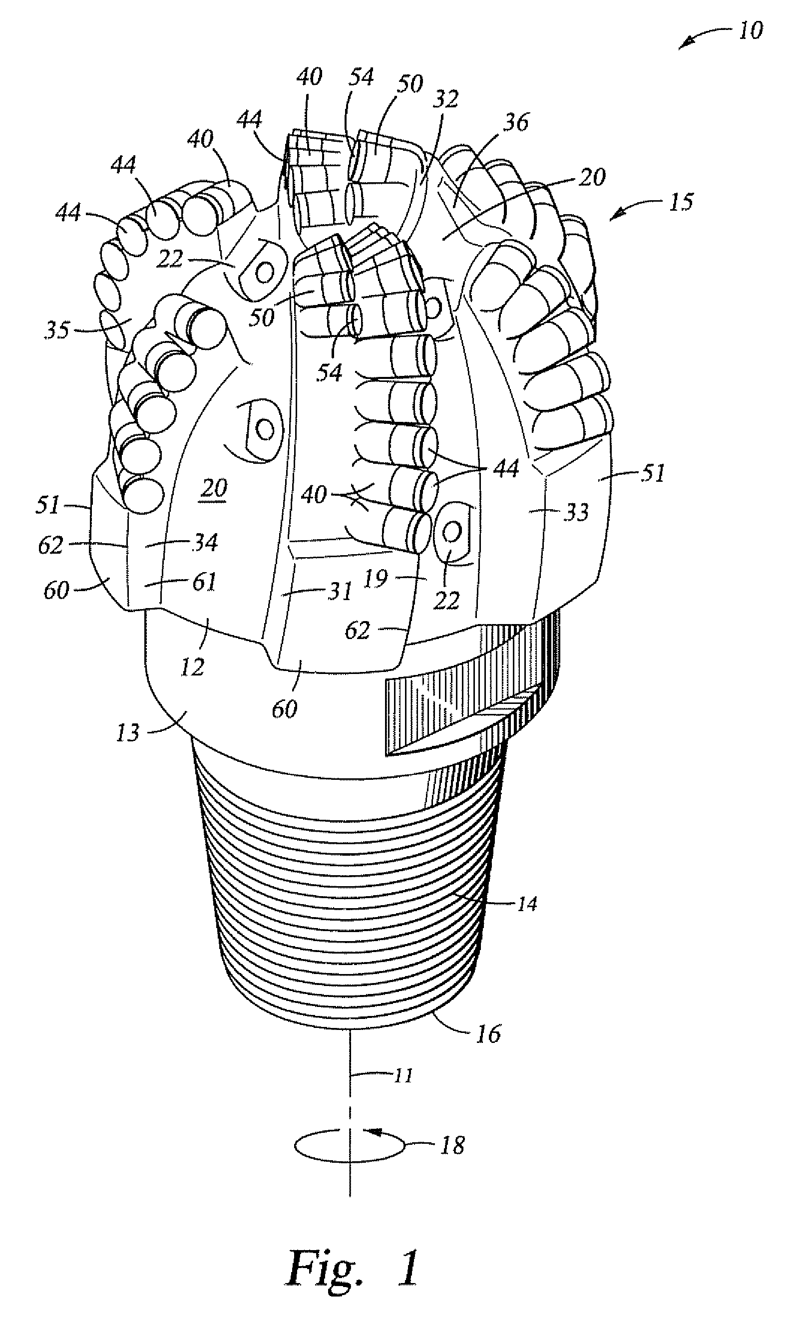
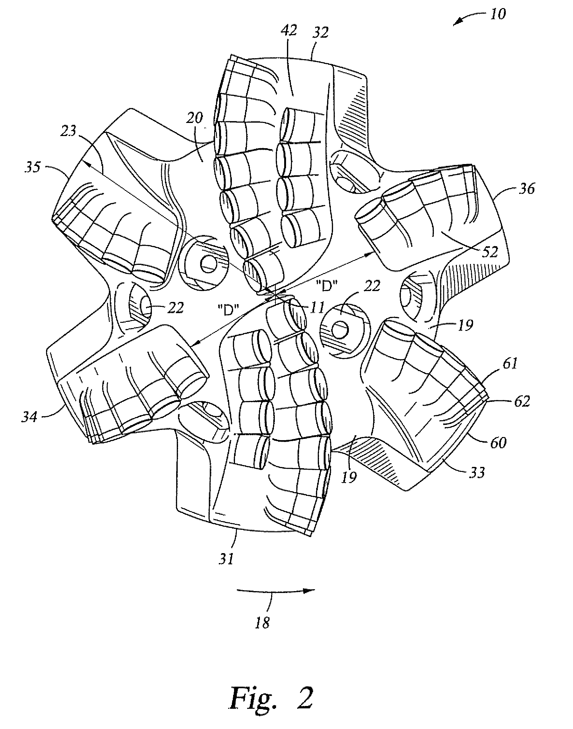
[0014] These and other needs in the art are addressed in one embodiment by a drill bit for drilling a borehole in earthen formations. In an embodiment, the bit comprises a bit body having a bit face comprising a cone region, a shoulder region, and a gage region. In addition, the bit comprises at least one primary blade disposed on the bit face, wherein the at least one primary blade extends into the cone region. Further, the bit comprises a plurality of primary cutter elements mounted on the at least one primary blade in the cone region. Still further, the bit comprises a plurality of backup cutter elements mounted on the at least one primary blade in the cone region, wherein the at least one primary blade has a cone backup cutter density and a shoulder backup cutter density, and wherein the cone backup cutter density of the at least one primary blade is greater than the shoulder backup cutter density of the at least one primary blade.

[0015] These and other needs in the art are add...


PUM


Abstract

A drill bit for drilling a borehole in earthen formations. In an embodiment, the bit comprises a bit body having a bit face comprising a cone region, a shoulder region, and a gage region. In addition, the bit comprises at least one primary blade disposed on the bit face, wherein the at least one primary blade extends into the cone region. Further, the bit comprises a plurality of primary cutter elements mounted on the at least one primary blade in the cone region. Still further, the bit comprises a plurality of backup cutter elements mounted on the at least one primary blade in the cone region, wherein the at least one primary blade has a cone backup cutter density and a shoulder backup cutter density, and wherein the cone backup cutter density of the at least one primary blade is greater than the shoulder backup cutter density of the at least one primary blade.

Description

CROSS-REFERENCE TO RELATED APPLICATIONS [0001] Not Applicable. STATEMENT REGARDING FEDERALLY SPONSORED RESEARCH OR DEVELOPMENT [0002] Not Applicable. BACKGROUND [0003] 1. Field of the Invention [0004] The invention relates generally to earth-boring drill bits used to drill a borehole for the ultimate recovery of oil, gas, or minerals. More particularly, the invention relates to drag bits and to an improved cutting structure for such bits. Still more particularly, the present invention relates to drag bits with backup cutters on primary blades, [0005] 2. Background of the Invention [0006] An earth-boring drill bit is typically mounted on the lower end of a drill string and is rotated by rotating the drill string at the surface or by actuation of downhole motors or turbines, or by both methods. With weight applied to the drill string, the rotating drill bit engages the earthen formation and proceeds to form a borehole along a predetermined path toward a target zone. The borehole thus ...

Claims


Application Information

Patent Timeline
IPC IPC(8): E21B10/08
CPCE21B10/43E21B10/36
Inventor CISNEROS, DENNIS
Owner SMITH INT INC
Why Eureka
Try Eureka