
Compensating for Non-Uniform Illumination of Object Fields Captured by a Camera

a technology of object field and compensation technique, applied in the field of processing captured digital imaging data, can solve the problems of non-uniform illumination, non-uniform illumination, non-uniform illumination compensation technique, etc., and achieve the effect of low cost and not adversely affecting the performance of the digital image processing path

Inactive Publication Date: 2007-11-15
QUALCOMM INC
View PDF12 Cites 23 Cited by
  • Summary
  • Abstract
  • Description
  • Claims
  • Application Information

AI Technical Summary

Benefits of technology

[0006] Such non-uniform illumination compensation techniques have application to digital cameras and other types of digital image capturing devices employing one or more illumination sources but are not limited to such optical photo system applications. The techniques may be implemented at a low cost, require a minimum amount of memory, and operate at the same rate as the digital image data being modified is obtained from the photo-sensor, thereby not adversely affecting the performance of the digital image processing path. This is accomplished by applying correction factors in real time to the output signals of the photo-sensor in order to compensate for an undesired intensity variation across the photo-sensor.

Problems solved by technology

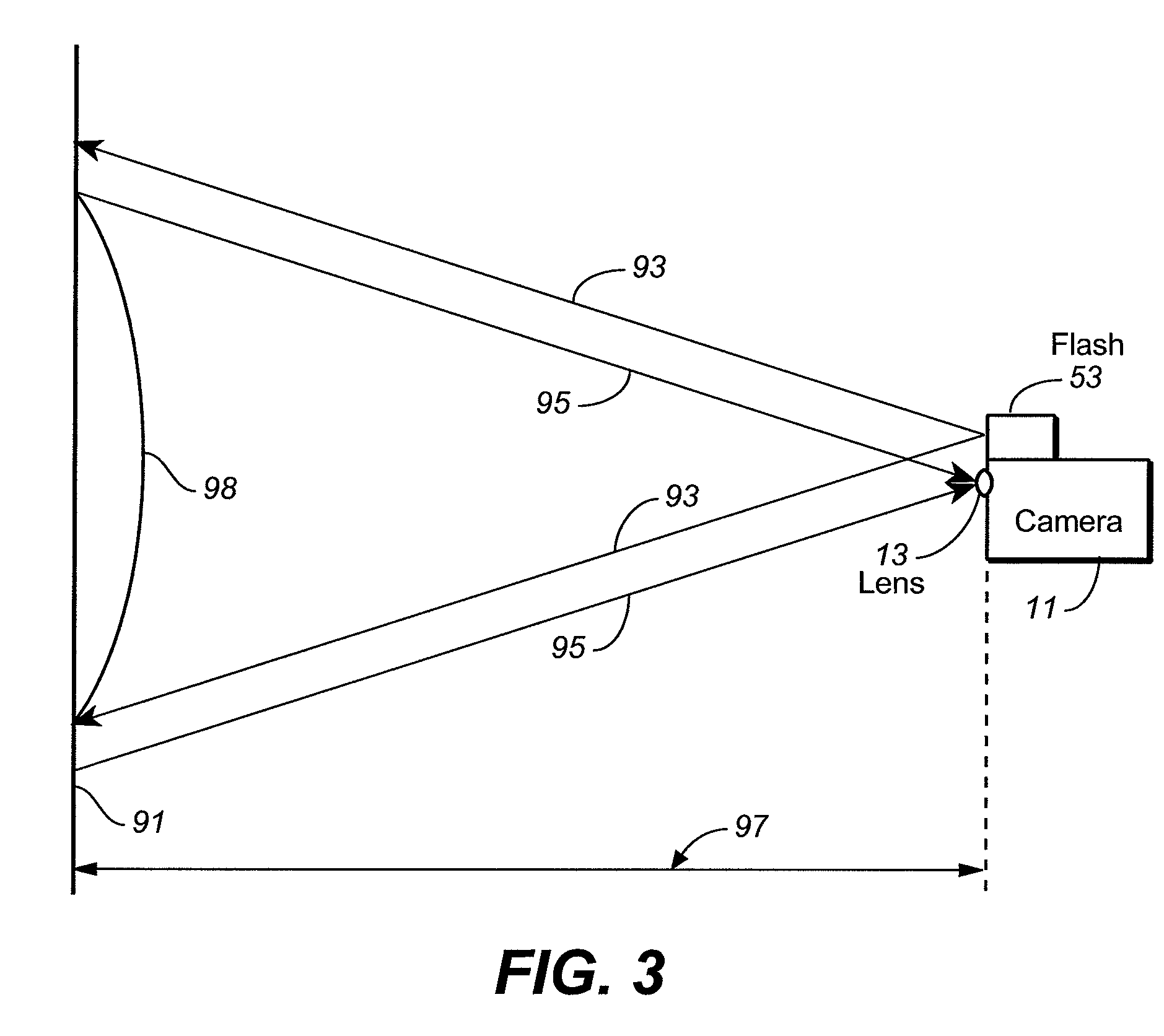
An illumination source may produce non-uniform illumination across an image field.
Non-uniform illumination may be attributed to imperfections in or other characteristics of an illumination source, improper alignment of an illumination source in relation to the x-y position of the image plane of the photo-sensor employed, and possibly other factors that may be present in a particular system.
Such non-uniform illumination compensation techniques have application to digital cameras and other types of digital image capturing devices employing one or more illumination sources but are not limited to such optical photo system applications.

Method used


Image

  • Compensating for Non-Uniform Illumination of Object Fields Captured by a Camera
  • Compensating for Non-Uniform Illumination of Object Fields Captured by a Camera
  • Compensating for Non-Uniform Illumination of Object Fields Captured by a Camera

Examples


specific embodiment

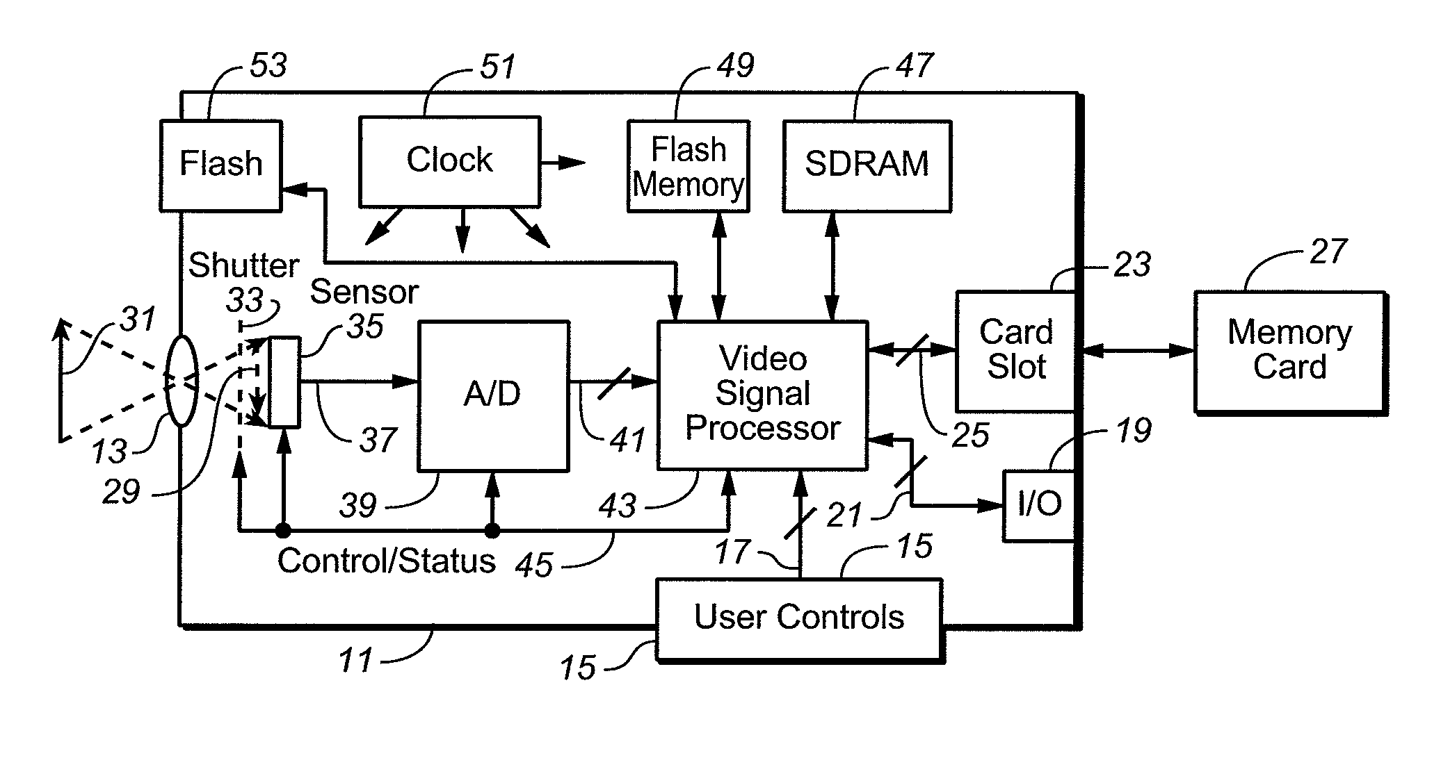
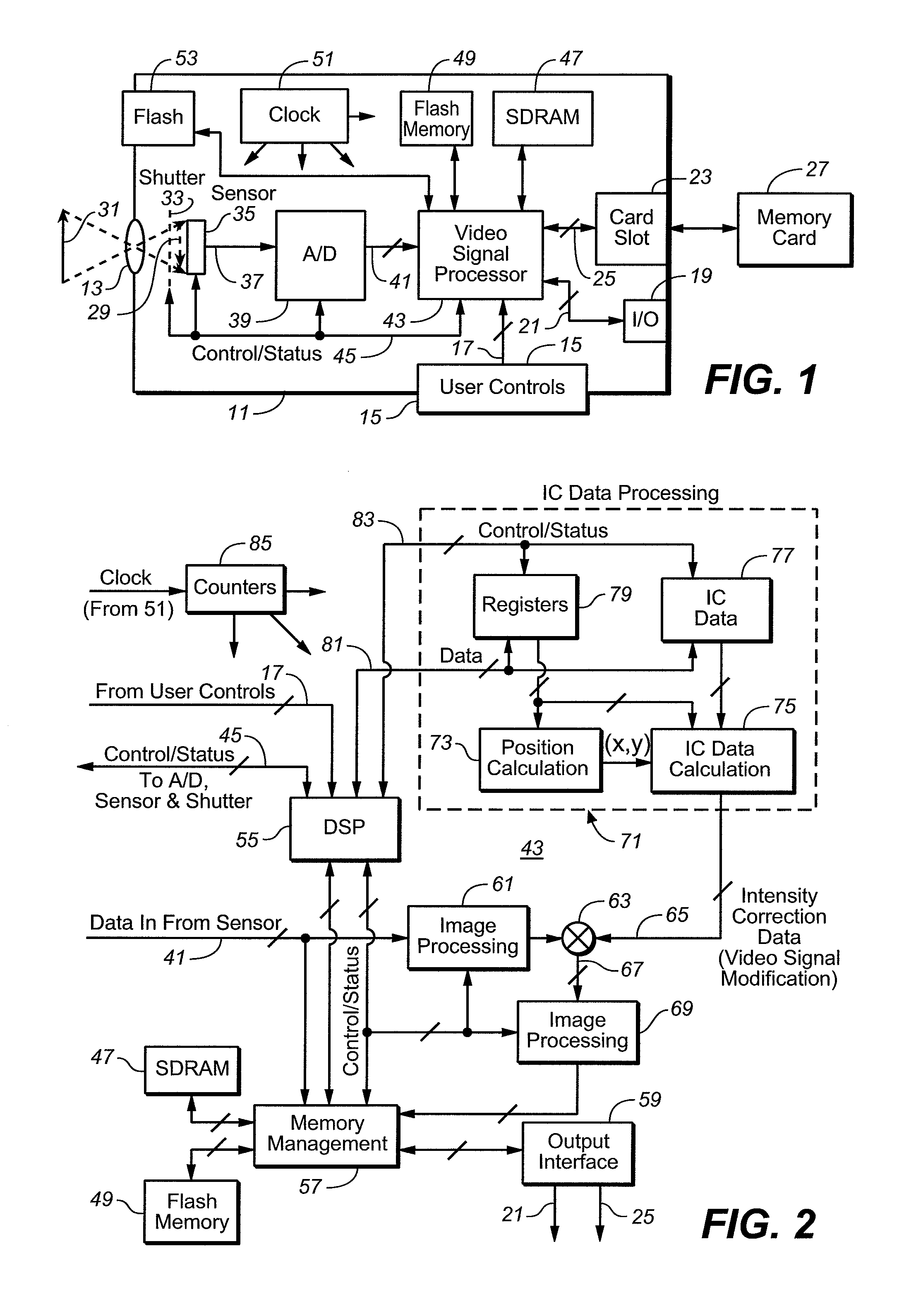
[0035] In this embodiment, non-uniform illumination correction factors for an optical photo system of a digital camera, digital video capturing device or other type of digital imaging device, are derived during a calibration procedure. This calibration is performed by imaging a surface having uniform optical properties onto the photo-sensor employed by the device being calibrated. One example of such a surface is a uniform mid-level gray target. The individual pixel intensity values of an image of such a target are captured and the slope values for the individual rectangles of the grid across the photo-sensor are calculated and stored in a memory within the device being calibrated. Image modification data and parameters are generated once for each camera at a final stage of its manufacture and then are permanently stored in the non-volatile memory 49 (FIG. 2). These data are then loaded through lines 81 into the memories 77 and 79 each time the system is initialized, under control o...


PUM


Abstract

Techniques for modifying data of an image that can be implemented in a digital camera, video image capturing device and other optical systems are provided to correct for non-uniform illumination appearing in data obtained using one or more illumination sources from a two-dimensional photo-sensor. In order to correct for these variations, a small amount of modification data is stored in a small memory within the optical system. According to a specific embodiment, non-uniform illumination correction factors are derived during a calibration procedure by illuminating a surface having uniform optical properties with the non-uniform illumination source and imaging that illuminated surface onto the photo-sensor.

Description

CROSS-REFERENCE TO RELATED APPLICATION [0001] This is related to another application of Shimon Pertsel entitled “Techniques for Modifying Image Field Data Obtained Using Illumination Sources,” being filed concurrently herewith. FIELD OF THE INVENTION [0002] This invention relates generally to techniques of processing captured digital imaging data obtained using one or more illumination sources, and, more specifically, to processing binary digital image data obtained using one or more illumination sources to correct for variations across an imaged optical field such as, for example, to compensate for non-uniform illumination. BACKGROUND [0003] Digital cameras image scenes onto a two-dimensional sensor such as a charge-coupled-device (CCD), a complementary metal-on-silicon (CMOS) device or other type of light sensor. These devices include a large number of photo-detectors (typically three, four, five or more million) arranged across a small two dimensional surface that individually ge...

Claims


Application Information

Patent Timeline
Patent Type & Authority Applications(United States)
IPC IPC(8): H01L27/00G03B15/03H04N5/235H04N5/335H04N9/07
CPCH04N5/2354H04N23/74
Inventor PERTSEL, SHIMON
Owner QUALCOMM INC
Learn More