Damper Apparatus

a technology of damper and cylinder, which is applied in the direction of shock absorbers, cycle springs, cycle equipments, etc., can solve the problems of damper material, sideways or lateral extrusion forces, and prior art devices have largely failed to meet the needs of damper materials, so as to reduce torque angle and shearing forces

Inactive Publication Date: 2007-11-15
RIAS TECH INT +1
View PDF23 Cites 12 Cited by
  • Summary
  • Abstract
  • Description
  • Claims
  • Application Information

AI Technical Summary

Benefits of technology

[0019] Preferably, one or both of the first and second materials have a plurality of lobes provided thereon at the interface with the damper material, the lobes being rounded in general form so as to substantially minimise torque angle and shearing forces when one material is moved relative to the other.

Problems solved by technology

Unfortunately, these prior art devices have proven largely inadequate, with the damper material breaking down through shearing forces induced therein in use, or through the damper material being forced / extruded outwardly / laterally, or being caused to bulge, from its housing.
The act of press-fitting places certain stresses on the damper material, for example shearing forces, and results in sideways or lateral extruding forces.
Consequently, there is little torque resistance and considerable extrusion of the damper material in use.
Again, the presence of the key introduces similar problems to those resulting from the toothed arrangement described in U.S. Pat. No. 6,755,432.
The smooth face of the inner shaft to which the damper material is bonded results in shearing forces in the damper material at that interface, where the area of interface between the damper material and the inner shaft is small, and again provides little torque resistance.
Any effort to prevent the lateral extrusion of the damper material only serves to increase the negative aspects of shearing forces and resultant fracturing of the damper material.
There is a significant friction penalty associated with side containment seen in the response and return of the damper material.
This is at least in part due to the Mullins effect that acts to impede full recovery of the damper material.
As such, the damping material is subject to compression-set in use, again inhibiting full functionality of the damper material.

Method used


Image

  • Damper Apparatus
  • Damper Apparatus

Examples


Embodiment Construction

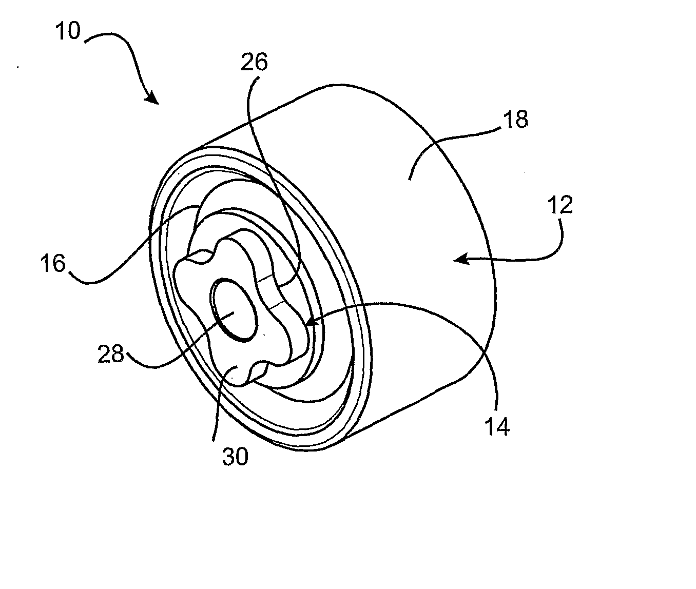
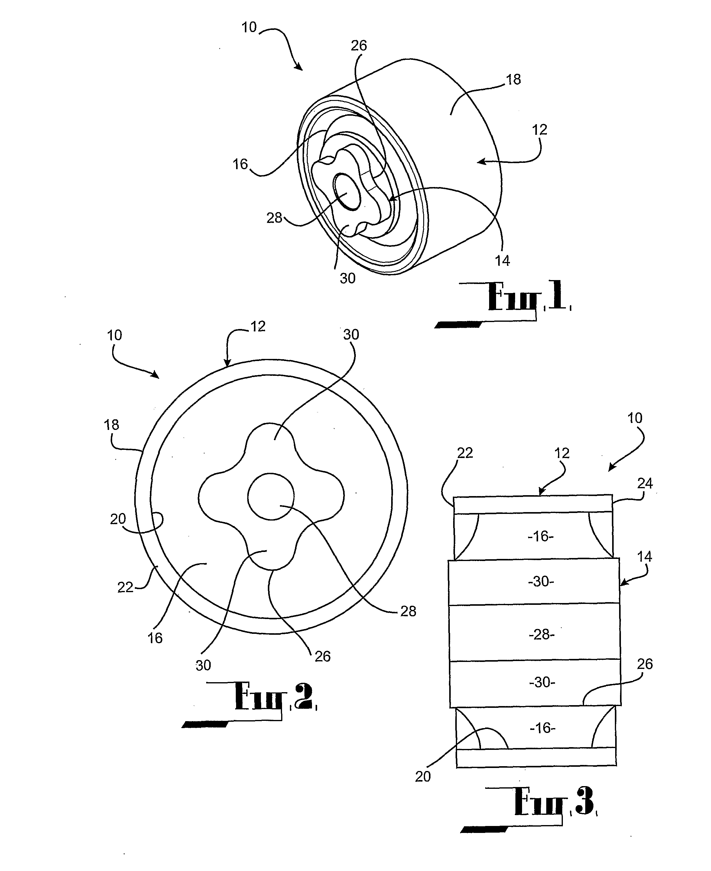
[0024] In FIGS. 1 to 3 there is shown a damper apparatus 10 adapted for use in torsion damping applications, the damper apparatus 10 comprising a first material, for example a housing 12 of generally circular configuration, a second material, for example an inner member 14, and a damper material 16 interposed there between. The housing 12 is provided with a radially disposed outer surface 18 and a radially disposed inner surface 20. The housing 12 further comprises a first lateral surface 22 and a second lateral surface 24. The damper material 16 is bonded directly to the inner surface 20 of the housing 12 and is further bonded to an outer surface 26 of the inner member 14. These bonding surfaces may be termed interfaces between the respective materials.

[0025] The inner member 14 has defined therein a transversely oriented inner core 28. The inner member 14 further comprises four (4) equally spaced radially extending lobes or projections 30. The radial projections 30 are rounded an...


PUM


Abstract

A damper apparatus (10) comprising a housing (12), an inner member (14) and a damper material (16) interposed there between, the damper material (16) being bonded to both the housing (12) and inner member (14), whereby at least one or other of the housing (12) and inner member (14) are able to rotate or be rotated respectively in a substantially concentric manner, the inner member (14) provided in a form or configuration presenting a limited torque angle to the damper material (16).

Description

FIELD OF THE INVENTION [0001] The present invention relates to a damper apparatus. More particularly, the damper apparatus of the present invention is intended for use in a wide variety of applications where energy absorption and springs are applicable. Amongst many applications for the damper apparatus of the present invention is in the suspension systems provided on bicycles, cycles and like conveyances. BACKGROUND ART [0002] Various shock absorbing or suspension arrangements have been demonstrated previously, with application to bicycles in particular, utilising what is described as either a damper assembly, a torsional shock absorber or torsion spring arrangement. See in this regard the disclosure of each of U.S. Pat. No. 5,975,550 (Schonfeld), U.S. Pat. No. 6,755,432 (Muser) and U.S. Patent Application Publication US 2001 / 0011806 A1 (Muser). Each of the arrangements described in these documents utilise an outer shell or housing and an inner shaft arranged to allow generally con...

Claims


Application Information

Patent Timeline
Patent Type & Authority Applications(United States)
IPC IPC(8): F16F7/04B60G7/02B60G7/04B60G11/23B60G13/04B62K25/04F16F1/38F16F13/04
CPCB60G7/02B60G11/23B60G2202/1424B60G2204/125F16F1/38B60G2204/41B62K25/04B62K2201/02B60G2204/143B60G13/04F16F7/04
Inventor VARRONE, ANTONIOCONTARINO, ALDO
Owner RIAS TECH INT
Why Eureka
Try Eureka