Magnetic Shield in the End Area of the Stator of a Three-Phase Generator

Inactive Publication Date: 2007-11-15
ALSTOM TECH LTD
View PDF18 Cites 12 Cited by
  • Summary
  • Abstract
  • Description
  • Claims
  • Application Information

AI Technical Summary

Benefits of technology

[0011] One of numerous aspects of the present invention therefore to attempt to avoid the abovementioned disadvantages of the prior art. Another aspect of the present invention is based on the technical problem of providing shielding over an area for components on the stator of a three-phase generator, which reduces the additional losses and preve

Problems solved by technology

One major source of additional losses in three-phase generators occurs in the metallic structural parts in the end area of the stator.
Parasitic magnetic fields, caused by currents in the end windings of the stator winding and rotor winding, produce eddy currents in these parts, which results in additional losses.
Furthermore, casing parts, in particular walls and ribs close to conductors, may also be at risk.
Eddy currents can cause considerable energy losses, the so-called eddy-current losses, in which energy is taken from the magneti

Method used


Image

  • Magnetic Shield in the End Area of the Stator of a Three-Phase Generator
  • Magnetic Shield in the End Area of the Stator of a Three-Phase Generator
  • Magnetic Shield in the End Area of the Stator of a Three-Phase Generator

Examples


Embodiment Construction

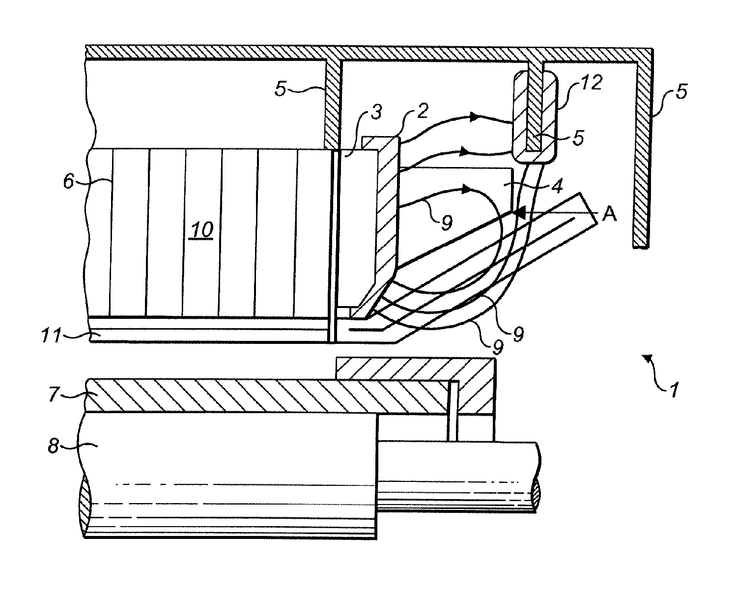
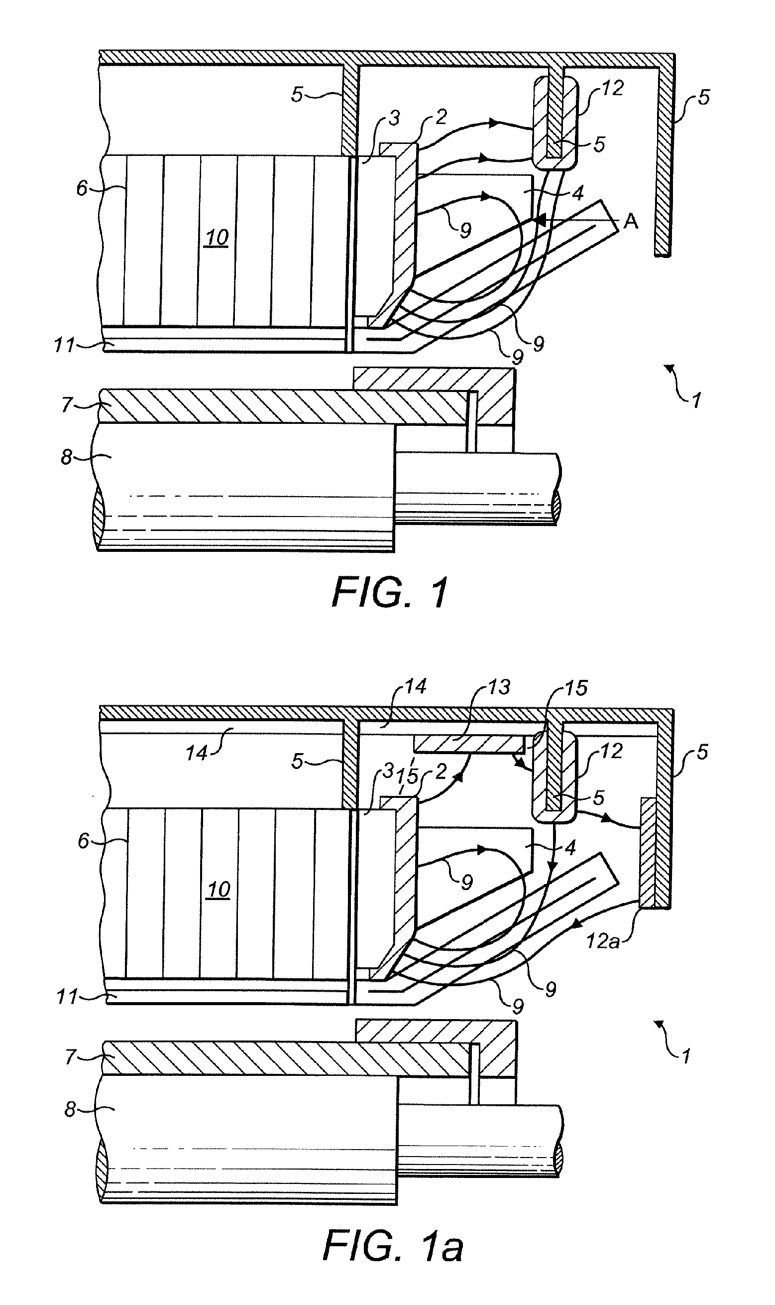
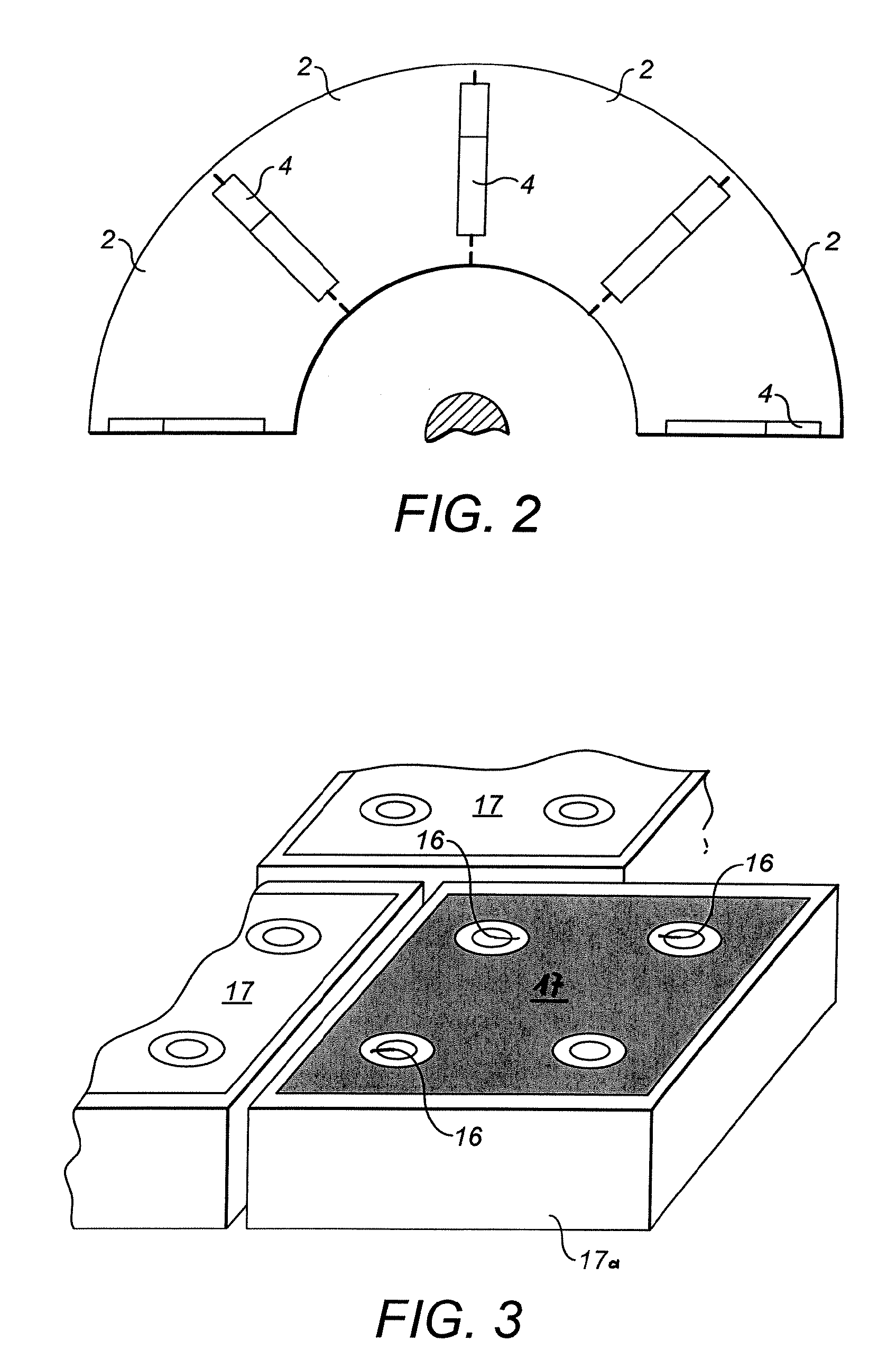
[0040]FIG. 1 shows a detail of a schematically illustrated three-phase generator with one advantageous embodiment of a shield according to the invention, in the form of a section view. FIG. 2 shows a partial view in the direction of the arrow A in FIG. 1.

[0041] The three-phase generator 1, which is illustrated schematically in FIG. 1, has a rotor body 8 in which rotor windings 7 are arranged in recesses, which are not illustrated. Furthermore, the three-phase generator 1 has a stator 10, which has a stator core 6. The rotor is arranged such that it can rotate concentrically in the stator core 6 and is terminated at the end, at the level of the end winding, by metallic pressure plates 3, for example composed of steel or aluminum. The stator core 6 is held in a casing 5.

[0042] The stator core 6 is fitted with a stator winding 11. The free ends of the stator winding 11, the so-called end windings, are held by supports 4, which are themselves mounted on the pressure plate 3. As can be...


PUM

PropertyMeasurementUnit
Temperatureaaaaaaaaaa
Thicknessaaaaaaaaaa
Thicknessaaaaaaaaaa

Abstract

A shield (2) for components on the stator (10) of a three-phase generator (1), with at least one pressure plate (3) or the like being arranged at the end on the stator core (6), is distinguished in that the shield (2) is composed essentially of a magnetically permeable composite material of low electrical conductivity. A method for production of a shield such as this includes the pressing and heat-treatment of appropriate composite particles. This overcomes the disadvantages of the prior art and provides a shield for components on the stator of a three-phase generator, which reduces the additional losses and prevents a build up of heat. Furthermore, this results in a solution which can be produced and installed easily and at low cost, and which can also easily be retrofitted to existing installations. Furthermore, three-dimensional finite element design methods can be used for optimized guidance of the magnetic field.

Description

[0001] This application claims priority under 35 U.S.C. § 119 to Swiss application number no. 00544 / 06, filed 31 Mar. 2006, the entirety of which is incorporated by reference herein. BACKGROUND [0002] 1. Field of the Invention [0003] The invention relates to a magnetic shield for components on a stator of a three-phase generator. A production method is also specified for a corresponding shield. [0004] 2. Brief Description of the Related Art [0005] One major source of additional losses in three-phase generators occurs in the metallic structural parts in the end area of the stator. Parasitic magnetic fields, caused by currents in the end windings of the stator winding and rotor winding, produce eddy currents in these parts, which results in additional losses. These additional losses generally make up about 0.05% to 0.1% of the efficiency of a turbogenerator. A major aim in this field of technology is therefore to reduce these additional losses as much as possible. A further aim at the...

Claims


Application Information

Patent Timeline
IPC IPC(8): H02K5/02H02K15/12
CPCH02K3/42Y10T29/49009H02K11/0005H02K11/014H02K11/0141
Inventor DRUBEL, OLIVERJOHO, REINHARDAREND, PETER
Owner ALSTOM TECH LTD
Why Eureka
Try Eureka