Induction lighting system

a technology of induction lighting and lighting components, applied in the direction of lighting and heating apparatus, magnetic discharge control, fixed installation, etc., can solve the problems of irreversible damage to electronic ballasts, heat dissipation problems, etc., and achieve the effect of improving the insulation of components, low cost, and low cos

Inactive Publication Date: 2007-11-15
LAU KENNETH
View PDF16 Cites 17 Cited by
  • Summary
  • Abstract
  • Description
  • Claims
  • Application Information

AI Technical Summary

Benefits of technology

[0009]It is a further object of this invention to improve the insulation of components within induction lighting enclosures.
[0010]It is a further object of this invention to p

Problems solved by technology

Associated with this induction lighting system is a heat dissipation problem, caused by radiated heat from the induction lamp to the heat sensitive high-frequency electronic ballast i

Method used


Image

  • Induction lighting system
  • Induction lighting system
  • Induction lighting system

Examples


Embodiment Construction

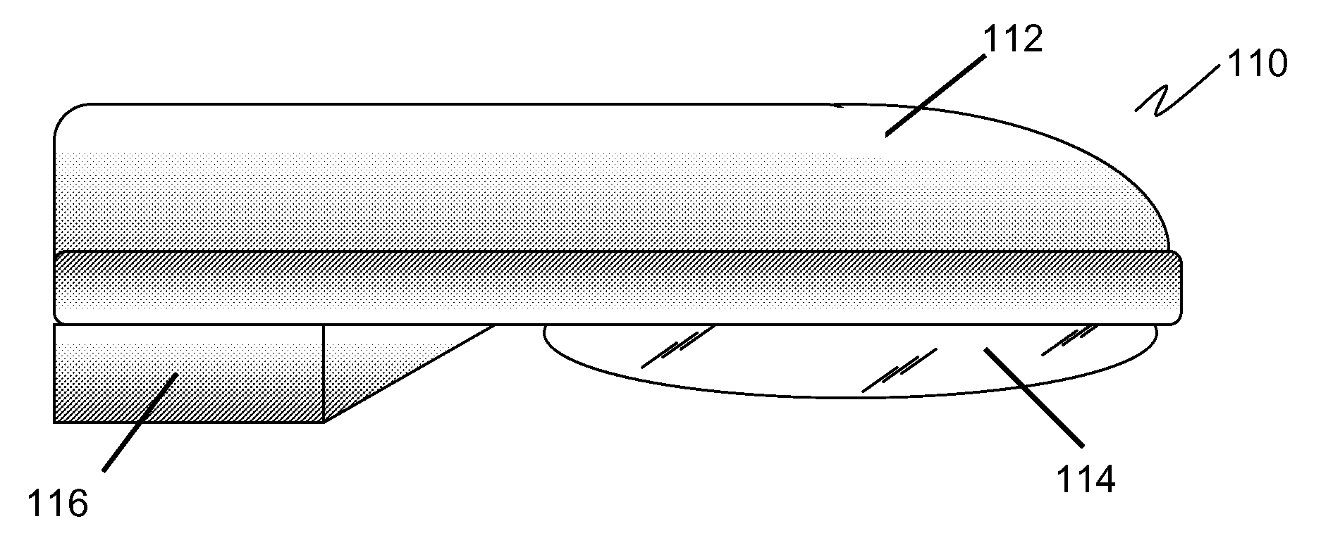
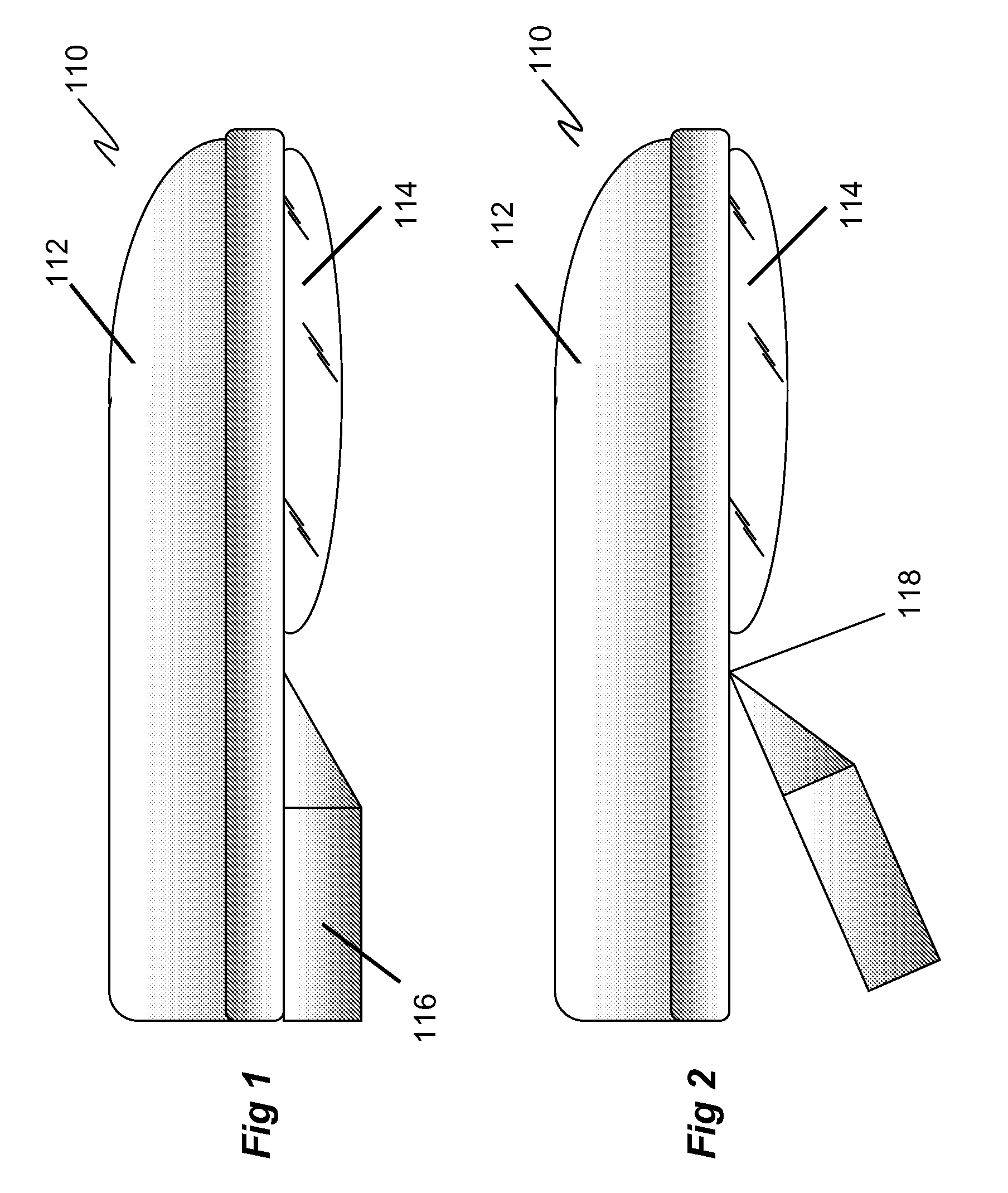
[0018]FIG. 1 and FIG. 2 show the general configuration of a cobra head induction lighting fixture 110. There is an upper housing 112 that contain an interior socket structure within which a lamp or light bulb can be mounted. The street lighting fixture is closed by a transparent or translucent lens 114.

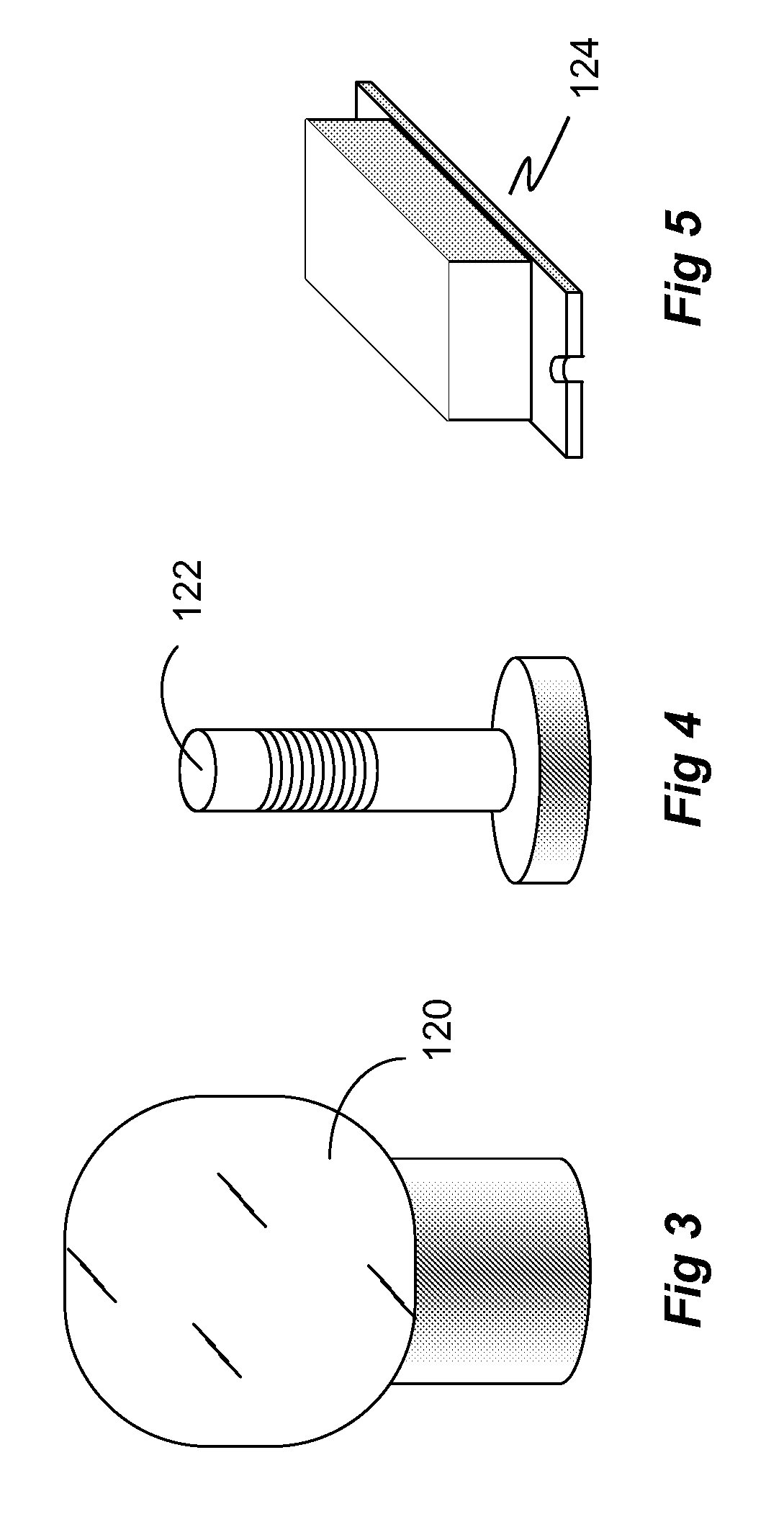
[0019]FIG. 3 shows typical induction vessel or lamp 120. There are other lamp shapes and configurations possible. FIG. 4 shows the induction coupler 122 which mates with the induction vessel 120 during installation. FIG. 5 shows a power stabilizer 124 electronic device, also known as a generator or ballast, that powers the induction lighting system 110.

[0020]In FIG. 6, there is a gate enclosure 116 that swings down via a detachable hinge 118, revealing the electronic components of the light fixture. Within the gate enclosure 116 are several components.

[0021]FIG. 6 shows the preferred embodiment of the solution to the heat dissipation problem. The present invention consists of a gate h...


PUM


Abstract

An improved induction lighting system is presented where the electronic power supply device powering the induction lamp is insulated and an extensive set of heat sink fins is provided to control the temperature of the power supply. Reduction of power supply device temperature in this manner greatly extends the operational life of these devices.
The improved induction lighting system is designed to be retrofitted into existing induction lighting systems, in all indoor and outdoor lighting applications.

Description

RELATED APPLICATIONS[0001]This application extends and completes Provisional Patent Application 60 / 797,164, filed on May 3, 2006.FIELD OF THE INVENTION[0002]This invention is related to the field of induction lighting, used in both outdoor and indoor lighting.BACKGROUND OF THE INVENTION[0003]There is a new type of induction lighting system available for sale that can last approximately 100,000 hours before replacement. It is used in applications such as street lighting fixtures that are generally described as a “cobra head”, because of their shape.[0004]Associated with this induction lighting system is a heat dissipation problem, caused by radiated heat from the induction lamp to the heat sensitive high-frequency electronic ballast inside the light fixture. Reducing the operating temperature of the lighting fixture by improving the radiation of generated heat can extend the life of these induction lighting systems.[0005]Prior art street lighting fixtures often have a hollow housing ...

Claims


Application Information

Patent Timeline
IPC IPC(8): H01J61/30
CPCH01J65/048
Inventor LAU, KENNETH
Owner LAU KENNETH
Why Eureka
Try Eureka