Automated, remotely-verified alarm system with intrusion and video surveillance and digital video recording

a remote monitoring and alarm system technology, applied in the field of intrusion alarm systems, can solve problems such as prone to false alarms, call being placed, and sensors only providing binary information

Active Publication Date: 2007-11-15
CHECKVIDEO
View PDF30 Cites 321 Cited by
  • Summary
  • Abstract
  • Description
  • Claims
  • Application Information

AI Technical Summary

Problems solved by technology

Failure to validate the alarm usually results in a call being placed to 3rd parties such as law enforcement officials.
In normal applications these types of sensors can only provide binary information indicating the active state of an alarm condition.
The main problem with conventional intrusion alarm systems is that they are very prone to false alarms due to inadequacies with existing technologies, and they provide no inexpensive means to visually validate an alarm remotely.
False alarm statistics are persistently in the high 90% range, an extremely costly false-positive problem.
Attempts have been made to try to address the false-alarm issue by deploying traditional closed circuit television (CCTV) cameras, however, these attempts have not met with success due to the cost of installation and equipment.
Another problem with conventional intrusion alarm systems is that they are very expensive both for the initial equipment cost and monthly recurring charge to the end-user.
Installation costs are typically passed on to the end-user.
In addition, these systems typically use a dial-up connection to communicate alarm conditions back to a central monitoring station making validation a slow and tedious process.
Another problem with conventional intrusion alarm systems is that they need to be actively monitored, generally requiring the use of a third-party monitoring service which can be prohibitively expensive and does substantially reduce the false positive problem.

Method used


Image

  • Automated, remotely-verified alarm system with intrusion and video surveillance and digital video recording
  • Automated, remotely-verified alarm system with intrusion and video surveillance and digital video recording
  • Automated, remotely-verified alarm system with intrusion and video surveillance and digital video recording

Examples


embodiment

An Exemplary Alarm Method Embodiment

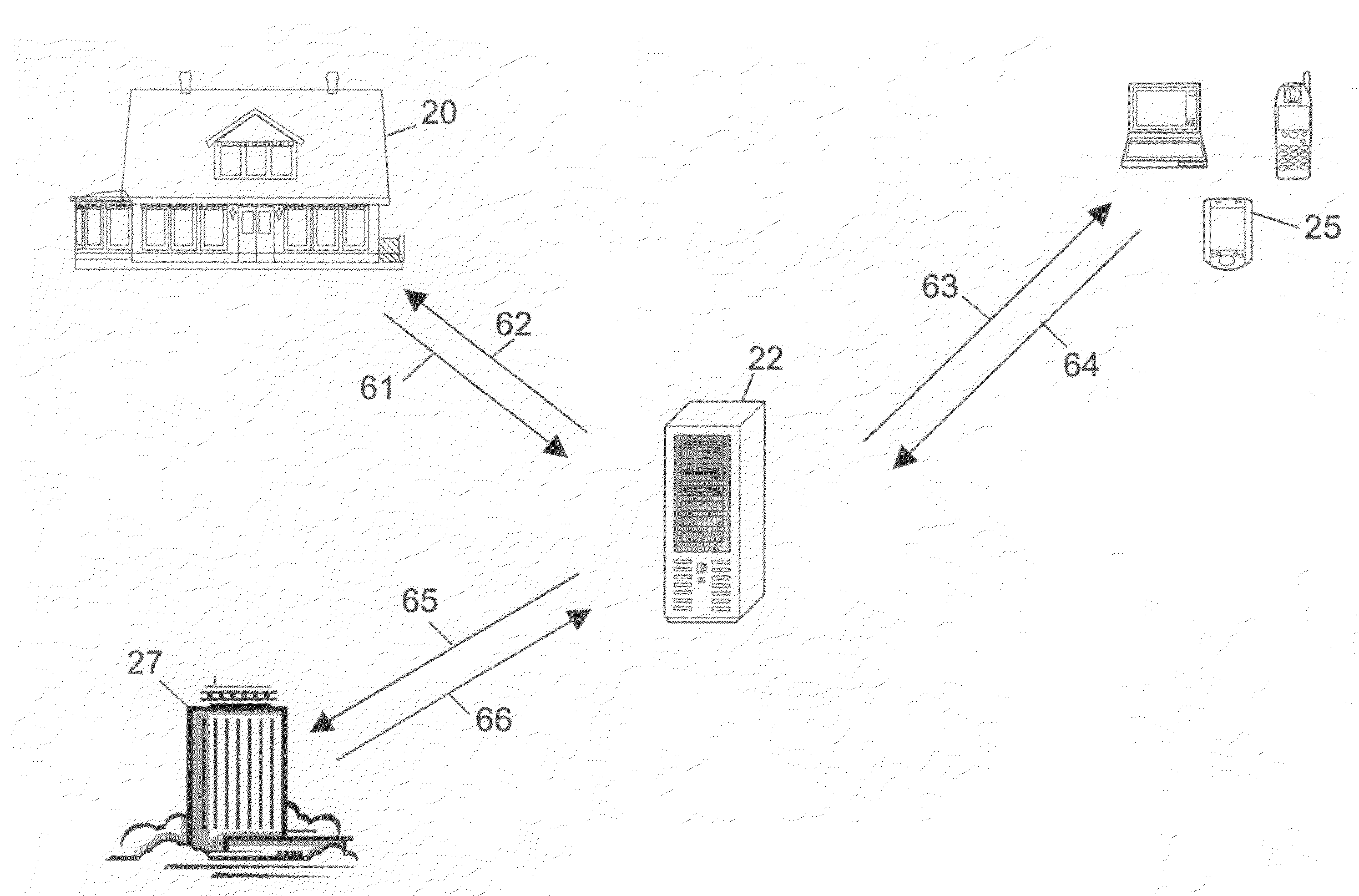
[0094]With reference to FIG. 7, a simplified description of an embodiment of the invented alarm system method is provided below for additional clarity, from the perspective of an end user employing the alarm system.

[0095]At 71, the alarm system captures image data and transmits a first signal to the SSMG. The SSMG receives the first signal, and transmits a second signal to a server portion, at 72, and then at 73, the server portion receives the second signal, and transmits a third signal to a device of the end user. The end user device receives the third signal, and at 74, the user views image data of the third signal at a display of the end user device. At 75, the end user inputs validation data (e.g., “Valid Alarm”, “Invalid Alarm”), and transmits a fourth signal from the end user device to the server portion. The server portion, at 76, receives the fourth signal, and if the fourth signal includes data indicating that the alarm is valid, the ser...


PUM


Abstract

An automated self-monitored alarm verification solution including at least a premises portion, a server portion, and an end user device portion. Alarm verification includes capturing by an image capture device at least one image in response to a detection event, and transmitting a first data signal including the image to a local signal processing device. The signal processing device transmits a second signal including at least a portion of the image to a remote hosted server according to at least a first set of predetermined parameters. After receiving the second signal, the server transmits a third signal including at least a portion of the image from the hosted server to a user device. Using the user device, a user views the image and indicates a validity status of the alarm based at least in part on the content of the image. Based at least upon either the validation status indicated by the user, or upon a failure to receive a message including a validation status from the user within a predetermined duration of time, the server portion may send an alarm signal to an emergency response service.

Description

RELATED APPLICATIONS[0001]The present application claims priority to U.S. Provisional Patent Application Ser. No. 60 / 800,505, entitled AUTOMATED SELF-MONITORED ALARM VERIFICATION SOLUTION and filed 15 May 2006, and U.S. Provisional Patent Application Ser. No. 60 / 800,504, entitled SELF-MONITORED INTRUSION AND VIDEO SURVEILLANCE SOLUTION WITH DIGITAL VIDEO RECORDING filed May 15, 2006, the disclosures of which are incorporated herein in their entirety by this reference.FIELD OF THE INVENTION[0002]The present invention relates generally to intrusion alarm systems, and more specifically it relates to an automated, remotely-monitored alarm verification solution for visually identifying the root cause of alarm events.BACKGROUND OF THE INVENTION[0003]It can be appreciated that intrusion alarm systems have been in use for years and are commonplace in commercial and residential applications. Typically, intrusion alarm systems are comprised of one or more passive sensors connected to a burgla...

Claims


Application Information

Patent Timeline
Patent Type & Authority Applications(United States)
IPC IPC(8): G08B29/00G08B1/00H04N7/18
CPCG08B13/19656G08B13/19663G08B13/19669G08B13/19684G08B13/19695G08B13/196G08B25/009H04N7/18G08B29/00G06T7/004G08B13/19602G08B25/008G06T7/70H04N5/76
Inventor JACKSON, RANDALL R.
Owner CHECKVIDEO
Why Eureka
Try Eureka