

Method and device for operating an optical display device
Inactive Publication Date: 2007-11-15
DAIMLER AG
View PDF3 Cites 6 Cited by
- Summary
- Abstract
- Description
- Claims
- Application Information
AI Technical Summary
Benefits of technology
[0011] In accordance with the invention, use is made of a method for operating an optical display device. The optical display device serves the purpose of displaying information pictorially to the user. In addition, the user's direction of view is detected as the information is being displayed. In a way according to the invention, one of the variables of the pictorial information can be varied as a function of the user's direction of view in the case of the method for operating the optical display device. In which case the variables of the pictorial information can be, in particular, the display variable, shape, color and intensity. The fact that the display variable of information varies as a function of the user's direction of view renders it possible for the first time for the user not to have to look directly at the optical display in order to take in information.
[0013] In an advantageous embodiment of the invention, the shape of the information to be displayed changes with the user's direction of view. If the user is not looking directly at the optical display, the pictorial information is displayed in another form than is otherwise the case. Before an item of information is displayed, it is advantageous to transform it into a symbolic descriptions. For example, the display of an analog measuring instrument is transformed into a digital display. The information is thereby displayed more accessibly to the user and can thereby be perceived more simply in a peripheral fashion.
[0014] In an advantageous refinement of the invention, the position of the information display on the optical display changes with the user's direction of view. If the direction of view is a direction to the left / right next to the optical display, the information is ideally displayed on the left / right-hand edge of the optical display. The information is correspondingly displayed in the direction at the edge of the optical display in which the direction of view exhibits the least deviation from the optical display. If the optical display is a display in which an image is projected (HUD, holographic display, . . . ), the information is displayed in a way similar thereto at the edge of the projected image. In addition, it is obvious in the case of such an optical display to project the complete image in a direction corresponding to the direction of view. Apart from the direction of view, it is greatly advantageous also to use the head position for evaluation purposes. Further facial features (for example nose and mouth) are taken into account in order to determine the head position from image data, as is described in the applicant's patent application having the publication number DE 10046859 A1. Since the position of the information display changes as a function of the direction of view and of the head position, the user can perceive the information effectively even in the case of indirect viewing contact.
[0015] In a further advantageous refinement of the invention, the intensity is changed with the user's direction of view when displaying the information. If the user looks directly at the optical display, the information is displayed with lesser intensity than is otherwise the case. It is particularly advantageous when the intensity of the optical display is varied continuously. The deviation of the direction of view from the direction of the optical display is evaluated in order to control the intensity. The information is displayed to the user in such a way that the latter senses a uniform brightness irrespective of the direction of view, and is not dazzled when looking directly at the optical display device.
[0017] A further advantageous refinement of the invention provides that the information display is continuously enlarged in the case when the user averts the direction of view from the optical display. The user can thereby recognize the information clearly at any time. By contrast, in the case when the user turns his direction of view to the optical display, the information display variable changes only after a prescribed time interval. This ensures that the user finds the information again immediately on the optical display.
Problems solved by technology
A disadvantage here is that the user must wear a spectacle frame without fail.
Method used
View moreImage
Smart ImageViewing Examples

Examples
Embodiment Construction
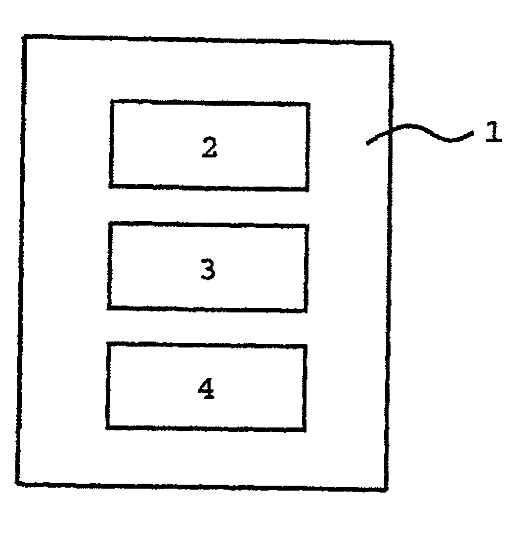
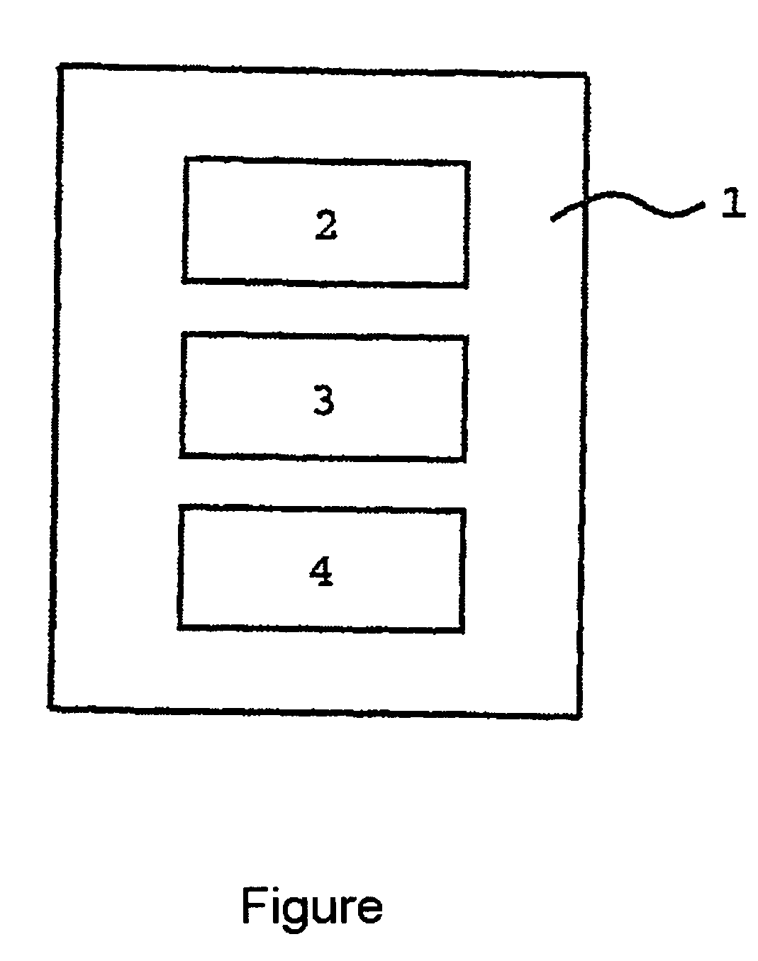
[0019] The FIGURE shows by way of example the schematic structure of the optical display device (1) according to the invention. The optical display device (1) in this case comprises an optical display (2) for displaying information. An image sensor (3) for detecting the user's direction of view and his head position. The optical display device (1) further comprises a data processing unit (4) for evaluating the detected data and for processing the information to be displayed.
Login to View More PUM
 Abstract
Poor visibility at night is a tiring and dangerous situation in traffic, feared by many drivers. As a result of poor visibility, the frequency of accidents at night is significantly higher than during the day with good visibility conditions. Cars are thus prospectively fitted with night vision systems, in order to increase safety in traffic. A night vision system used for this purpose generally comprises an illumination unit for illuminating the environment surrounding the vehicle, an image recording unit for collecting environmental data, and an image processing unit for evaluating the environmental data. So that the operation of the night vision system can be adapted to different situations, it must be designed in a flexible manner. To this end, the individual components of the night vision system must be able to be operated in different combinations. In order to achieve this, the components of the night vision system can be individually controlled by means of at least one control signal.
Description
BACKGROUND OF THE INVENTION [0001] 1. Field of the Invention [0002] The invention relates to a method for operating an optical display device, and to an optical display device for using the method. [0003] 2. Related Art of the Invention [0004] There are many different types of optical displays that are used for the most varied fields of application. The information displayed by means of an optical display is used in many instances as a control function or as additional information that is read out by the user when required. In order to avoid being distracted by the optical display, developments have been made in which the information to be displayed is projected directly into the user's field of view. These are so-called head-up displays (HUDs). For example, an HUD permits complete concentration on the road traffic, the driver no longer having to look away from the road in order to observe speed displays. In addition to speed displays, it is also possible for information relating to...
Claims
Login to View More Application Information
Patent Timeline
 IPC IPC(8): G09G5/00G02B27/00G02B27/01G06F3/048
CPCG02B2027/0187G02B27/01
InventorHAHN, STEFAN
OwnerDAIMLER AG