Quadrature sub-harmonic frequency down-converter

a sub-harmonic frequency and transformer technology, applied in the field of quadratic sub-harmonic frequency down-converter, can solve the problems of complex circuits, power-hungry, and need for two local oscillators and their incumbent circuitry, and achieve the effects of reducing increasing the complexity of circuits, and increasing the cost of circuits

Inactive Publication Date: 2007-11-15
COBHAM DEFENSE ELECTRONICS SYST CORP
View PDF9 Cites 33 Cited by
  • Summary
  • Abstract
  • Description
  • Claims
  • Application Information

AI Technical Summary

Problems solved by technology

One of the disadvantages of the heterodyning technique is that it requires two local oscillators and their incumbent circuitry, expense, and complexity.
A significant disadvantage of direct conversion, however, is the need for a local oscillator that oscillates all the way up at the FRF frequency (or very close to it, in the case of a low-IF technique).
Generally, the higher the frequency at which a circuit must operate, the more complex, power-hungry, and expensive that circuit tends to be.
Accordingly, direct frequency up-conversion and down-conversion in connection with these signals would require very high frequency (and therefore very complex, very expensive, and very power-hungry) local oscillators and phase locked loops (PLLs).

Method used


Image

  • Quadrature sub-harmonic frequency down-converter
  • Quadrature sub-harmonic frequency down-converter
  • Quadrature sub-harmonic frequency down-converter

Examples


Embodiment Construction

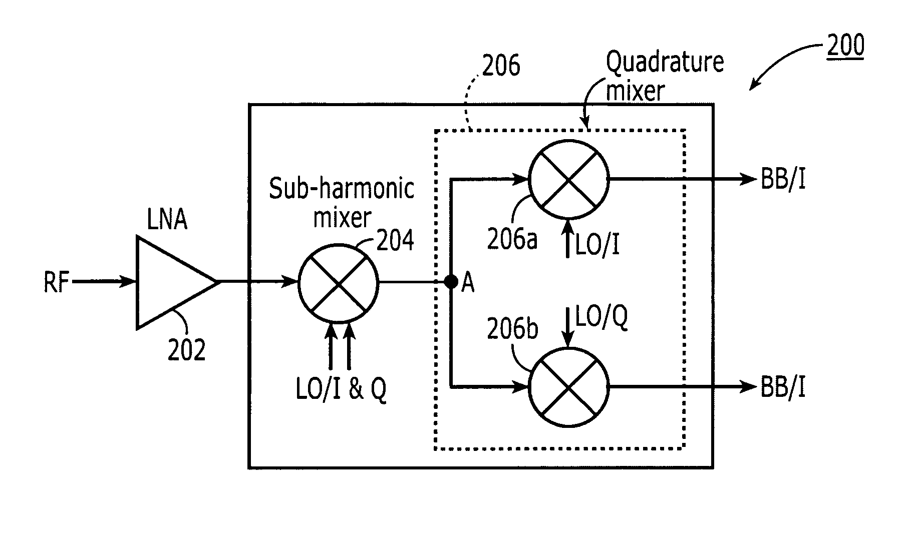
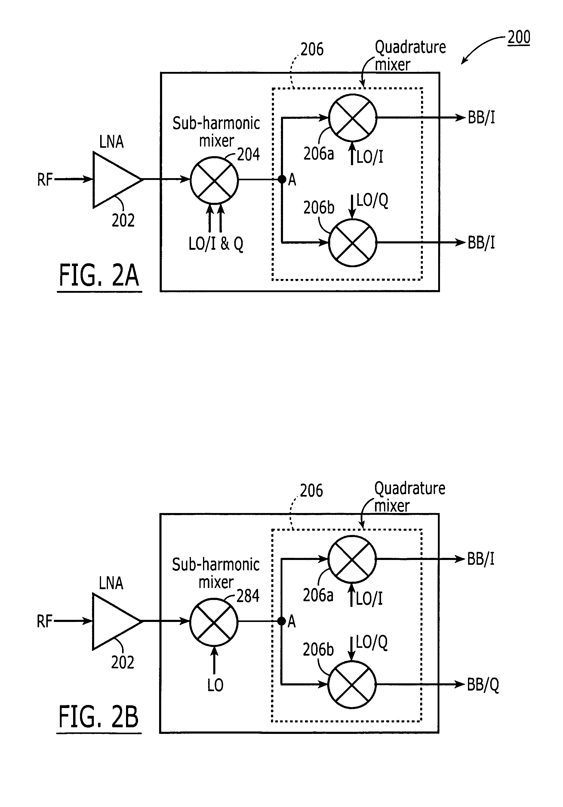
[0027] The present invention pertains to a quadrature sub-harmonic frequency down-converters and up-converters that frequency convert between baseband and and RF in two stages having the advantages of requiring only a single local oscillator frequency much lower than the received RF signal frequency.

[0028] The invention uses the two quadrature components of a single local oscillator signal. Using a down-converter as an example, the first stage, the RF signal is mixed with both components of a local oscillator signal (LO) at or about one third the RF frequency in a sub-harmonic mixer using multi-phase LO signals, in this case, two signals in quadrature, to produce an intermediate frequency output signal (IF) having a frequency of twice the local oscillator frequency minus the RF frequency. i.e., 2FLO−FRF=⅓FRF=FIF. In a second stage, that IF signal is split into two and supplied to a quadrature mixer that mixes the IF signal with the I component of the same local oscillator signal an...


PUM


Abstract

A method and apparatus for frequency down-converting a radio frequency (RF) signal to baseband in two steps using the two quadrature components of a single local oscillator. In the first stage, the RF signal is mixed with both components of the local oscillator signal (LO) in a sub-harmonic mixer to produce an intermediate frequency (IF) output signal having a frequency component at twice the local oscillator frequency minus the RF frequency, i.e., (2×LO)−RF=IF. In the second stage, the IF signal is split into two and supplied to a quadrature mixer that mixes the IF signal with the I component of the same local oscillator signal and separately mixes the IF signal with the Q component of the same local oscillator signal to produce an output signal comprising an I component and a separate Q component at baseband.

Description

FIELD OF THE INVENTION [0001] The invention pertains to radar and wireless communications systems, such as cellular telephone communications systems and television and radio communications systems. BACKGROUND OF THE INVENTION [0002] Generally, in any type of wireless communication system, baseband voice or data signals are carried on a radio frequency (RF) carrier frequency. Thus, circuitry must be provided in a transmitter that places the baseband signal on the RF carrier signal. This process is commonly termed frequency up-conversion and the circuitry that performs this process is commonly called a frequency up-converter. Likewise, in the receiver, the baseband signal must be extracted from the incoming RF receive signal picked up by the receive antenna. This process is commonly termed frequency down-conversion and the circuitry that performs this process is commonly called a frequency down-converter. [0003] There are several techniques in common use for performing frequency up-co...

Claims


Application Information

Patent Timeline
Patent Type & Authority Applications(United States)
IPC IPC(8): H04B1/26
CPCH03D7/1441H03D7/165H04B1/28H03D2200/0084H03D7/1458H03D7/1475H03D7/1433
Inventor CARREZ, FREDERIC
Owner COBHAM DEFENSE ELECTRONICS SYST CORP
Why Eureka
Try Eureka