Low-profile location pad

a location pad and low-profile technology, applied in the field of positioning tracking systems, can solve the problems of inaccurate measurement of vertical displacement of position sensors adjacent to this plane, degrade position measurement accuracy, etc., and achieve the effect of reducing height dimensions and low profil

Inactive Publication Date: 2007-11-15
BIOSENSE WEBSTER INC
View PDF19 Cites 142 Cited by
  • Summary
  • Abstract
  • Description
  • Claims
  • Application Information

AI Technical Summary

Benefits of technology

[0005] Some embodiments of the present invention provide location pads comprising multiple magnetic field generators having a low profile (i.e., a reduced height dimension). This arrangement is advantageous in a number of medical position tracking applications. For example, a thin horizontal array of field generators can be conveniently placed on an operating or catheterization table, directly underneath a region of interest of a patient's body. A position sensor in a medical probe, such as a catheter, or other object in the body senses the fields produced by the field generators and outputs signals that are processed to determine coordinates of the probe or other object.
[0008] To overcome this difficulty, in some embodiments of the present invention, the location pad comprises an auxiliary field generator, either within or outside of the location pad, which is oriented so as to generate an auxiliary magnetic field having a component parallel to the plane of the location pad at locations within the plane. By having the position sensor sense the two or more magnetic fields as well as the auxiliary magnetic field, the position tracking system is able to accurately measure the position of the position sensor even when it is located adjacent to the plane of the location pad.
[0009] In some embodiments, the position tracking system assists a physician in performing cardiac catheterization procedures. In these embodiments, a low profile location pad is placed on top of the catheterization table, underneath the patient's torso. A position sensor is fitted in the catheter inserted into the patient's heart. An additional reference position sensor may be attached to the patient's body, typically on the patient's back. Both sensors, and in particular the reference sensor, are adjacent to the plane of the location pad. Using the methods and systems described herein, the position tracking system can accurately track the positions of the catheter and the reference sensor.
[0016] In still another embodiment, the system includes a reference position sensor, which is attached to the body of the patient at a reference location adjacent to the common plane and is arranged to sense the auxiliary magnetic field and the magnetic fields generated by the two or more field generators so as to measure a position of the reference location. The reference position sensor may be arranged to accurately measure a vertical displacement of the reference location based on the sensed auxiliary magnetic field.

Problems solved by technology

In some cases, however, the proximity of the field generators to the tracked position sensor may degrade the position measurement accuracy.
For example, when the field generators comprise coils wound in the horizontal plane in order to reduce their height, measurements of vertical displacements of position sensors adjacent to this plane can be inaccurate.

Method used


Image

  • Low-profile location pad
  • Low-profile location pad
  • Low-profile location pad

Examples


Embodiment Construction

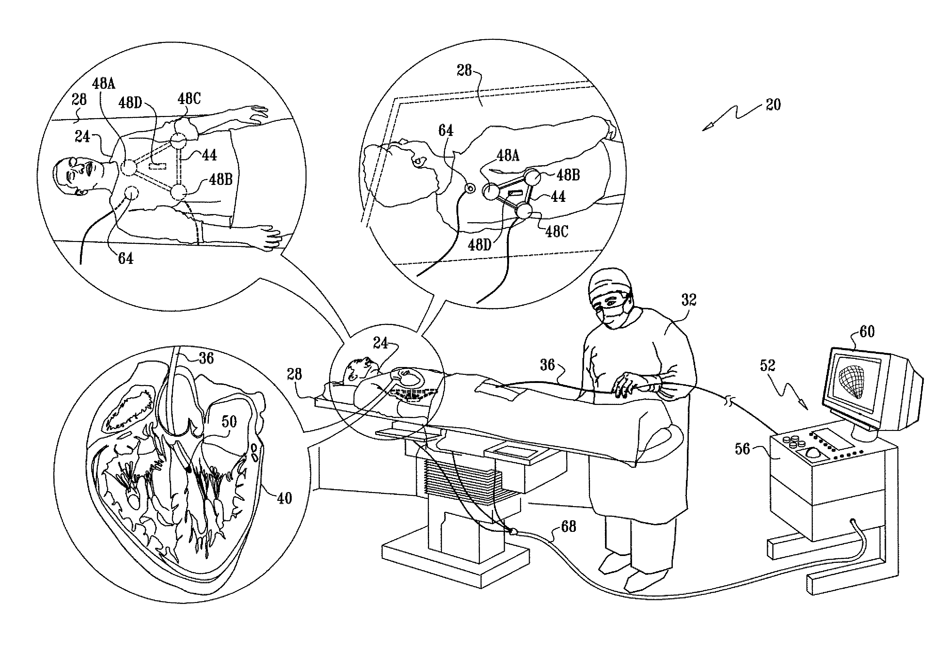
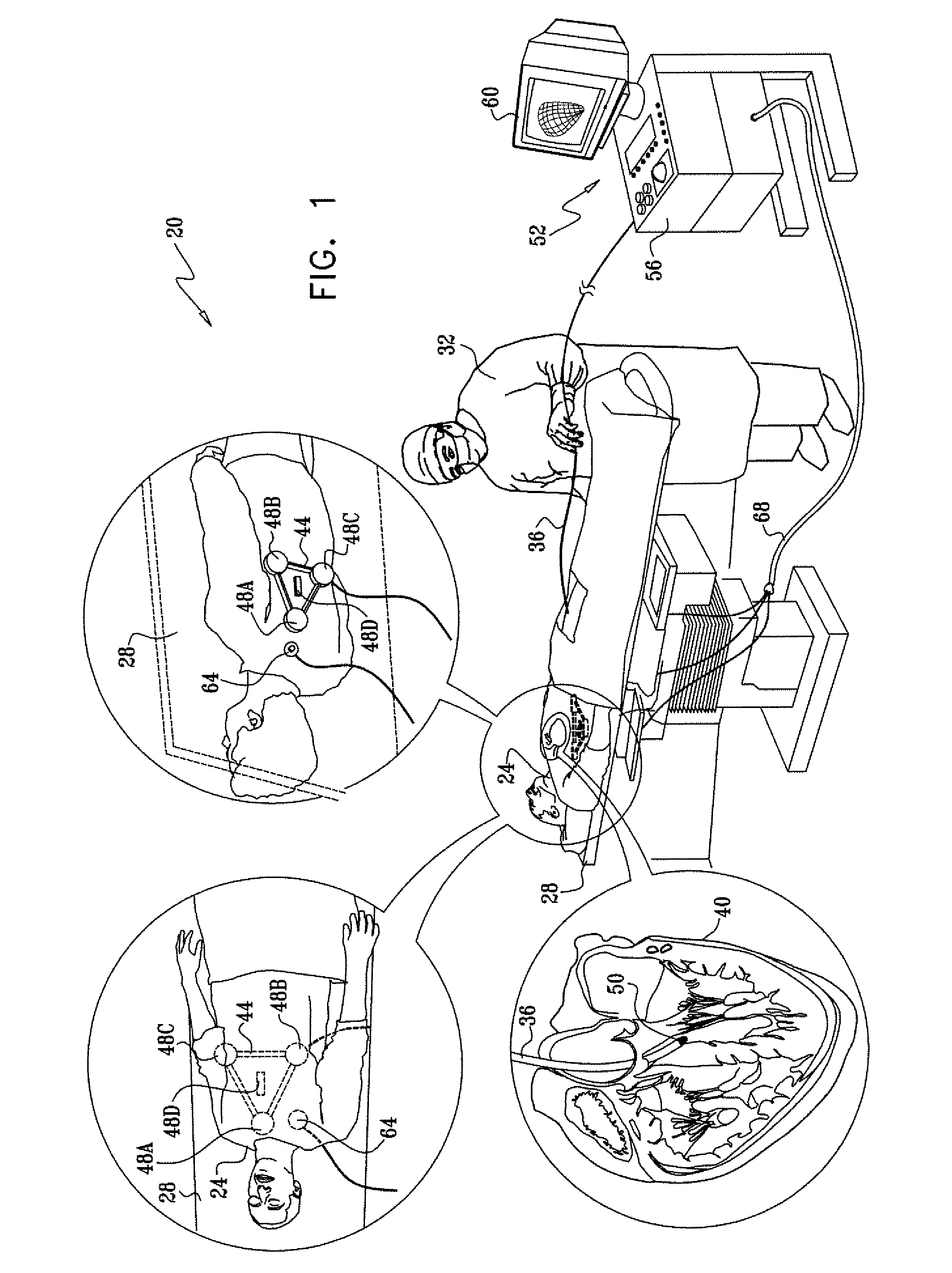
[0040]FIG. 1 is a schematic, pictorial illustration of a magnetic position tracking system 20 used in cardiac catheterization applications, in accordance with an embodiment of the present invention. A patient 24 lies on a catheterization table 28. A physician 32 inserts a catheter 36 into a chamber of a heart 40 of the patient. System 20 determines and displays the position and orientation coordinates of catheter 36 inside the heart.

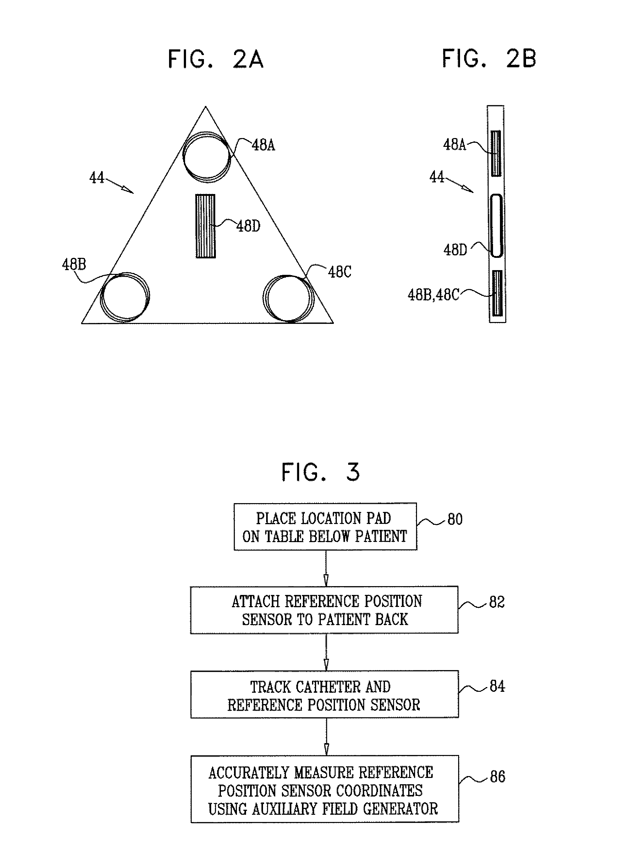
[0041] System 20 comprises a location pad 44, which comprises one or more field generators, such as field generating coils. In the exemplary configuration of FIG. 1, pad 44 comprises four field generating coils 48A . . . 48D. The location pad is placed on top of the catheterization table under the patient's torso, such that coils 48A . . . 48D are located in fixed, known positions external to the patient. The field generating coils generate magnetic fields in a predefined working volume around heart 40.

[0042] The operation of system 20 is similar to th...


PUM


Abstract

A magnetic position tracking system for performing a medical procedure on a patient who is positioned on an upper surface of a table includes a location pad, which is positioned on the upper surface of the table beneath the patient. The location pad includes one or more field generators, which are operative to generate respective magnetic fields and are arranged so that a thickness dimension of the location pad is no greater than 3 centimeters. A position sensor is fixed to an invasive medical device for insertion into a body of the patient, and is arranged to sense the magnetic fields so as to measure a position of the medical device in the body.

Description

FIELD OF THE INVENTION [0001] The present invention relates generally to position tracking systems, and particularly to location pads used in magnetic position tracking. BACKGROUND OF THE INVENTION [0002] Various methods and systems are known in the art for tracking the coordinates of objects involved in medical procedures. Some of these systems use magnetic field measurements. For example, U.S. Pat. Nos. 5,391,199 and 5,443,489, whose disclosures are incorporated herein by reference, describe systems in which the coordinates of an intrabody probe are determined using one or more field transducers. Such systems are used for generating location information regarding a medical probe, such as a catheter. A position sensor, such as a coil, is placed in the probe and generates signals in response to externally-applied magnetic fields. The magnetic fields are generated by magnetic field transducers, such as radiator coils, fixed to an external reference frame in known, mutually-spaced loc...

Claims


Application Information

Patent Timeline
Patent Type & Authority Applications(United States)
IPC IPC(8): A61B5/05
CPCA61B5/06A61B5/061A61B2019/5272A61B19/5244A61B2019/5251A61B5/065A61B5/062A61B2034/2072A61B34/20A61B2034/2051A61B1/045
Inventor GOVARI, ASSAFALTMANN, ANDRES CLAUDIOEPHRATH, YARON
Owner BIOSENSE WEBSTER INC
Why Eureka
Try Eureka