Method for Ablating Body Tissue

Active Publication Date: 2007-11-15
AURIS HEALTH INC
View PDF99 Cites 194 Cited by
  • Summary
  • Abstract
  • Description
  • Claims
  • Application Information

AI Technical Summary

Benefits of technology

[0014] One aspect of the invention provides a cardiac ablation system including an ablation catheter having an anchor adapted to support the ablation catheter within an atrium of a heart and an ultrasound emitter disposed radially outward from a rotation axis and from the anchor, and a control mechanism adapted to rotate the ultrasound emitte

Problems solved by technology

Current status of the Maze procedure for the treatment of atrial fibrillation, Seminars in Thoracic &

Method used


Image

  • Method for Ablating Body Tissue
  • Method for Ablating Body Tissue
  • Method for Ablating Body Tissue

Examples


first embodiment

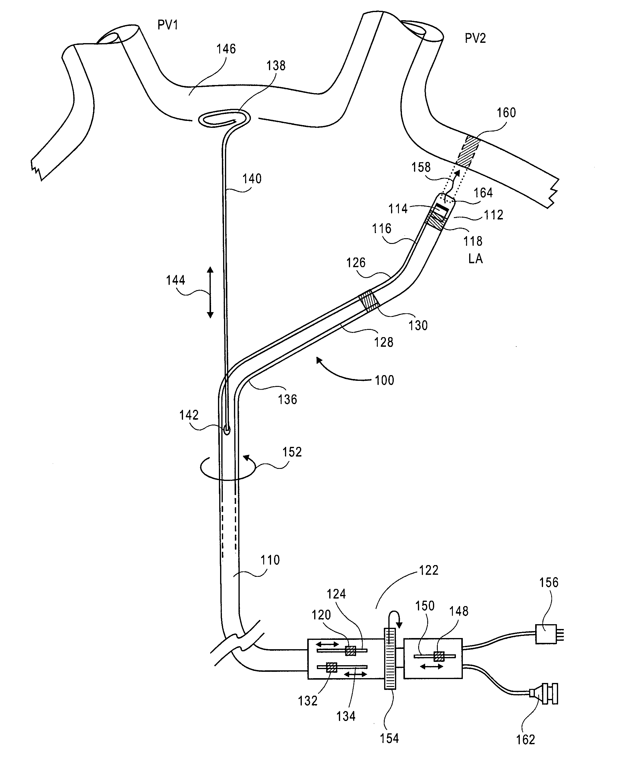
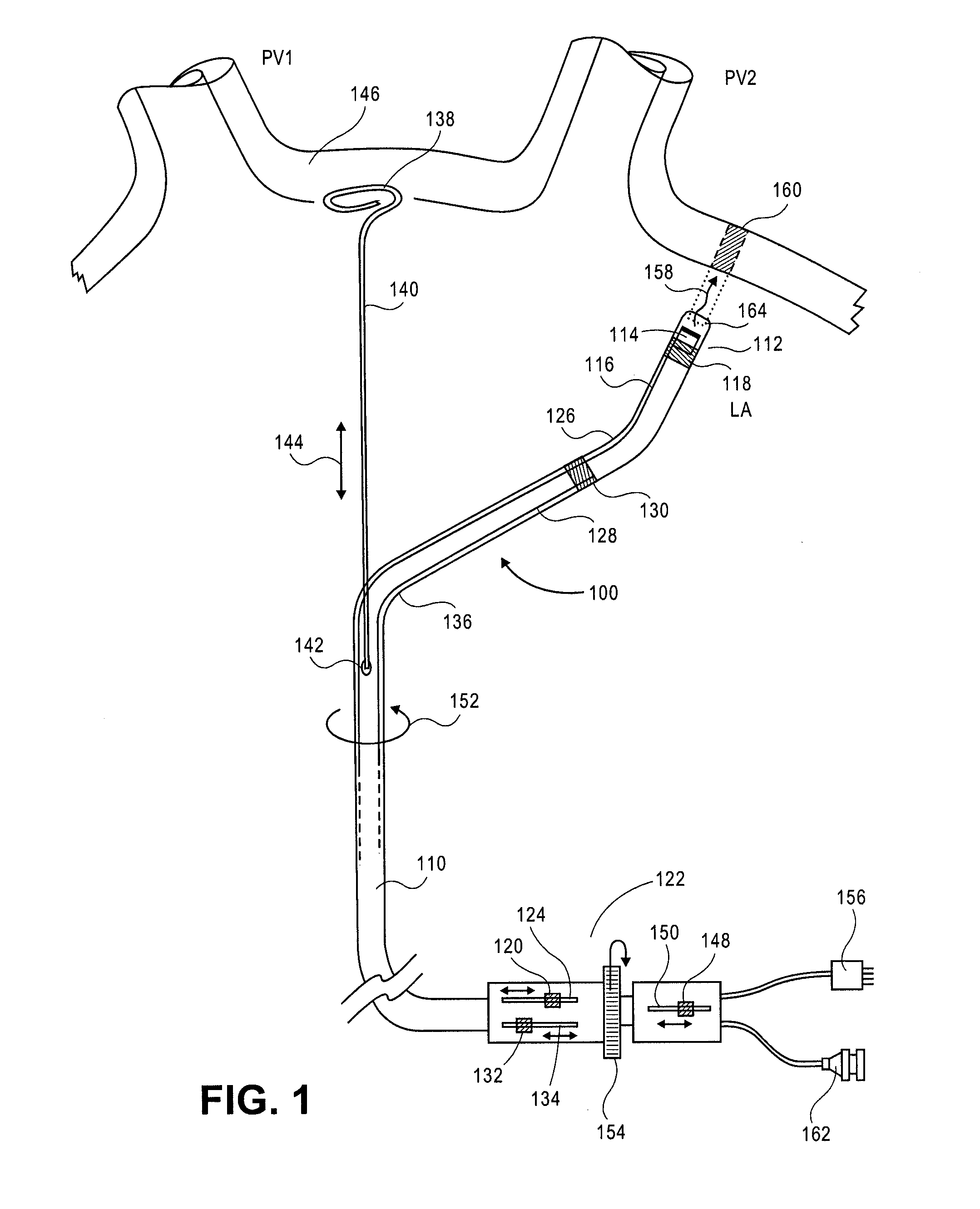
[0077] One aspect of the invention is shown in FIG. 1. As shown, the device 100 includes an elongate member that can be a catheter 110. In other implementations, the elongate member is a cannula, tube or other elongate structure having one or more lumens. The catheter 110 can be made of a flexible multi-lumen tube. As shown, the catheter 110 can include a distal tip assembly 112 positioned at a distal portion of the catheter 110. The tip assembly 112 can house an energy delivery structure, for example, an ultrasound transducer subassembly 114 (described in more detail in reference to FIG. 4).

[0078] Although the ablation device described herein includes a distal tip assembly having an ultrasound transducer as a source of ablation energy, it is envisioned than any of a number of energy sources can be used with various implementations of the invention. Suitable sources of ablation energy include but are not limited to, radio frequency (RF) energy, microwaves, photonic energy, and therm...

third embodiment

[0098] the invention including an alternative distal tip assembly arrangement is shown in FIG. 7. Various details, features and uses of this embodiment include those as described herein regarding other embodiments. In this embodiment an alternative transducer subassembly is provided as shown in detail in FIG. 8. As shown in FIG. 8, the ultrasound transducer 1320 can be mounted on an angled backing 1326. The angle of the backing can range between substantially 0-90°. In one implementation the angle is substantially 10-80o. In another implementation the angle is substantially 30-60°. In another implementation the angle is substantially 40-50°. In a further embodiment the angle is substantially 45°. The transducer can include a shape. In one implementation the transducer is in the shape of an elliptical disc. In another implementation the transducer has a rectangular shape. As shown in FIGS. 7 and 8, in one implementation the transducer 1320 can emit energy in the form of an ultrasound...

fourth embodiment

[0100] the invention including an alternative distal tip assembly arrangement is shown in FIG. 9, and the details of the tip assembly are shown in FIG. 10. Various details, features and uses of this embodiment include those as described herein regarding other embodiments. In this embodiment an alternative transducer subassembly is provided as shown in detail FIG. 10. As shown in FIG. 10, in this implementation, the ultrasound transducer 1420 is mounted at a distal portion of the distal tip assembly 1412. Further, the transducer 1420 is directed substantially toward the proximal direction. As illustrated, in this orientation the transducer 1420 can emit an ultrasound wave 1457 substantially parallel to the longitudinal axis of the distal tip assembly 1412.

[0101] As shown in FIG. 10, proximal to the transducer 1420 an angled reflector device can be mounted. For example, the reflector device can be a cylindrical reflector 1452 with having a face cut at an angle to the distal tip assemb...


PUM


Abstract

A cardiac ablation method including the following steps: inserting a treatment catheter into an atrium of a heart, the treatment catheter including an ultrasound emitter; positioning the ultrasound emitter to face heart tissue within the left atrium outside of a pulmonary vein; emitting ultrasound energy from the ultrasound emitter while rotating the ultrasound emitter about a rotation axis; and ablating heart tissue with the ultrasound energy to form a lesion outside of a pulmonary vein.

Description

CROSS-REFERENCE TO RELATED APPLICATIONS [0001] This application claims the benefit under 35 U.S.C. § 119 of U.S. Provisional Application No. 60 / 747,137, filed May 12, 2006, and of U.S. Provisional Application No. 60 / 919,831, filed Mar. 23, 2007, the disclosures of which are incorporated herein by reference as if fully set forth.INCORPORATION BY REFERENCE [0002] All publications and patent applications mentioned in this specification are herein incorporated by reference to the same extent as if each individual publication or patent application was specifically and individually indicated to be incorporated by reference. FIELD OF THE INVENTION [0003] In this invention we describe a device and a method for creating ablation zones in human tissue. More specifically, this invention pertains to the treatment of atrial fibrillation of the heart by using ultrasound energy. BACKGROUND OF THE INVENTION [0004] The condition of atrial fibrillation is characterized by the abnormal (usually very r...

Claims


Application Information

Patent Timeline
IPC IPC(8): A61B18/04
CPCA61B17/2202A61B18/1492A61B18/24A61B2017/00106A61B2017/00243A61B17/320068A61B2017/22024A61B2018/00029A61N7/022A61N2007/0078A61N7/02A61B2017/003A61B2017/320069
Inventor THAPLIYAL, HIRA V.GALLUP, DAVID A.ARENSON, JAMES W.
Owner AURIS HEALTH INC
Why Eureka
Try Eureka