Automotive wiper assembly

a technology for auto-disassembly and wiper blades, which is applied in the field of wiper blades, can solve the problems of reducing the effectiveness of the wiper blade in removing water from the windshield, and achieve the effect of enhancing the airfoil effect and reducing the tendency for lifto

Inactive Publication Date: 2007-11-22
ADM21 CO LTD +1
View PDF34 Cites 38 Cited by
  • Summary
  • Abstract
  • Description
  • Claims
  • Application Information

AI Technical Summary

Benefits of technology

[0027] The orientation of the stiffener at an offset angle from the central geometric plane of the blade defines an asymmetry in the blade, the wiping blade is in combination with a connector for engagement to the end of a wiper arm on a motor vehicle. The connector engages the wiper blade by connecting to the extending sides of the stiffener, the connector is asymmetrically formed to cancel the effect of the asymmetry in the orientation of the stiffener within the wiper blade so as to present the wiping edge of the wiper blade, when coupled to the wiper arm, to a windshield with a normal, substantially upright, vertical, orientation with the central plane of the wiper in a generally upright orientation with respect to the windshield.
[0078] When a connector in accordance with an embodiment of the invention is shaped so that the pressing force supplied by the end of the wiper arm is generally directed along or close to the central wiping edge plane of the wiper blade, the tendency for an undesirable torque to generated at the coupling with the wiper arm is reduced and the tendency for an undesirable deflection to occur in the wiping edge is also reduced. Thus, the wiping edge is pressed against the windshield with a balanced pressure which retains the desirable effect of having generally similar amounts of deflection arise irrespective of the direction that the wiper blade is being passed over a vehicle windscreen.

Problems solved by technology

This effect, particularly at high speeds, can reduce the effectiveness of the wiper blade in removing water from the windshield.

Method used


Image

  • Automotive wiper assembly
  • Automotive wiper assembly
  • Automotive wiper assembly

Examples


Embodiment Construction

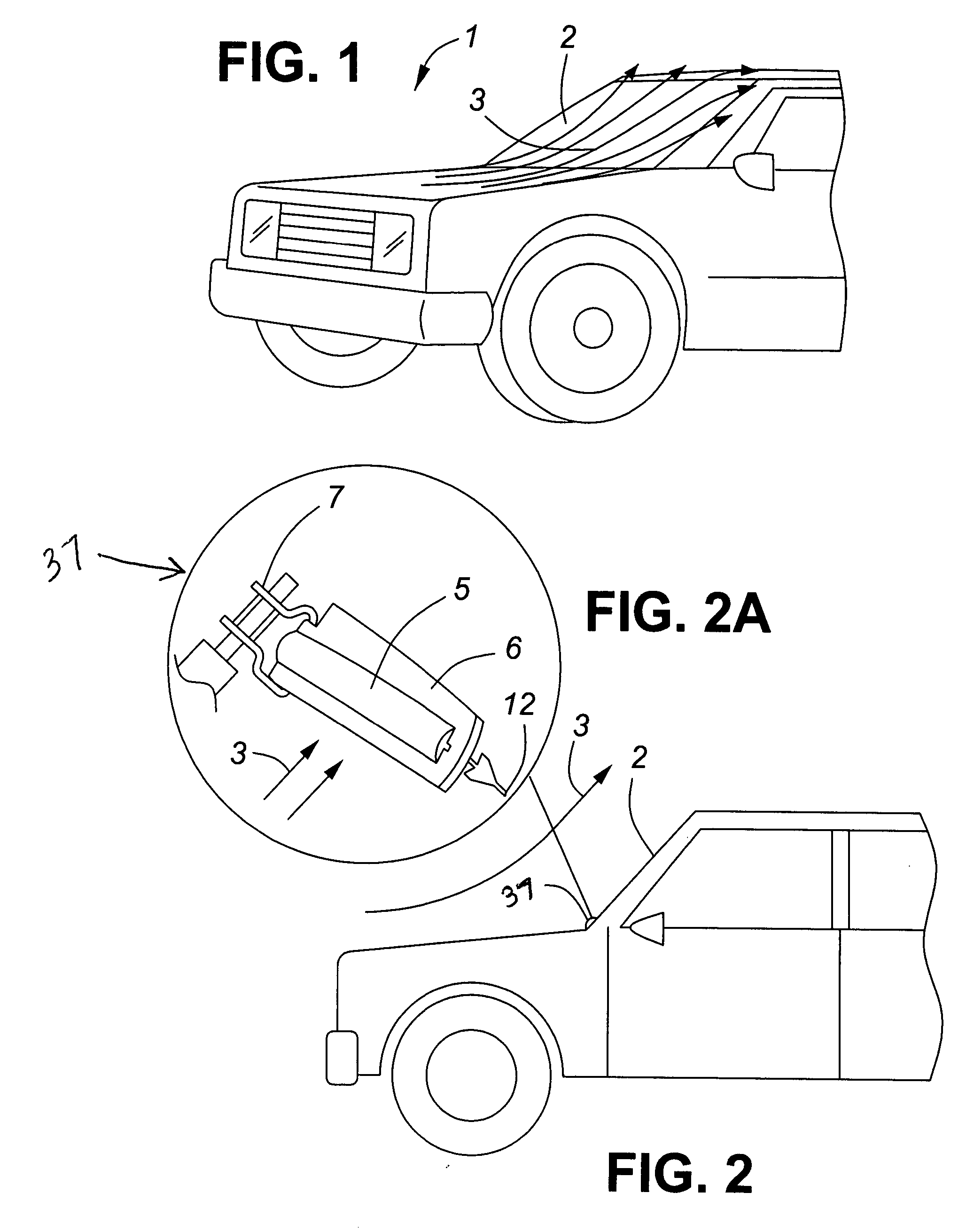
[0092]FIG. 1 depicts a vehicle 1 with windshield 2 advancing through airflow 3 whereby airflow 3 is deflected upwardly as it passes over the windshield 2.

[0093]FIG. 2 depicts a wiper blade assembly 37 comprising a wiper blade body 5, stiffener 6 and a connector 7. In FIG. 2A, the blade edge 12 is angled with respect to the blade body 5 but is presented to the windshield in an upright orientation.

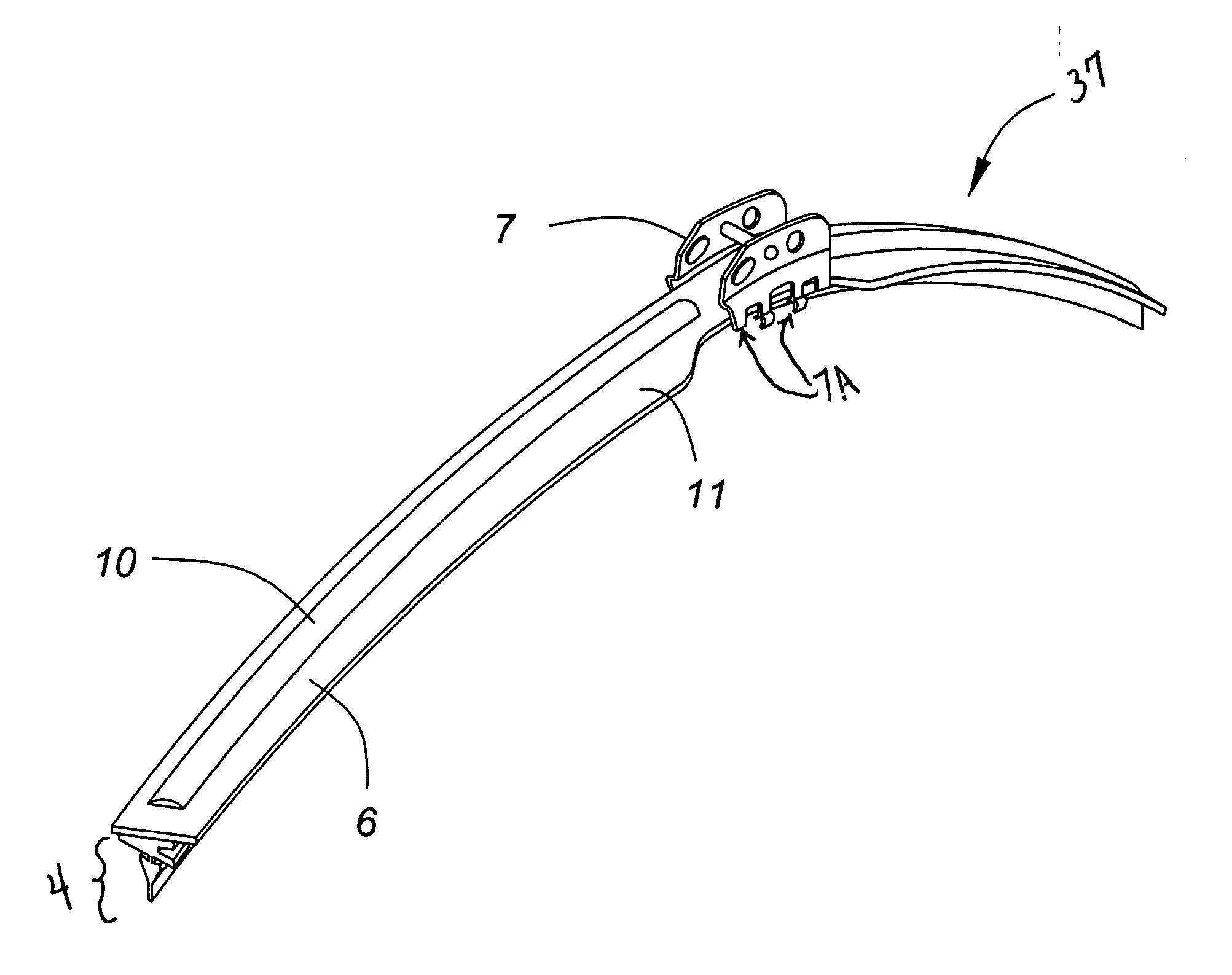
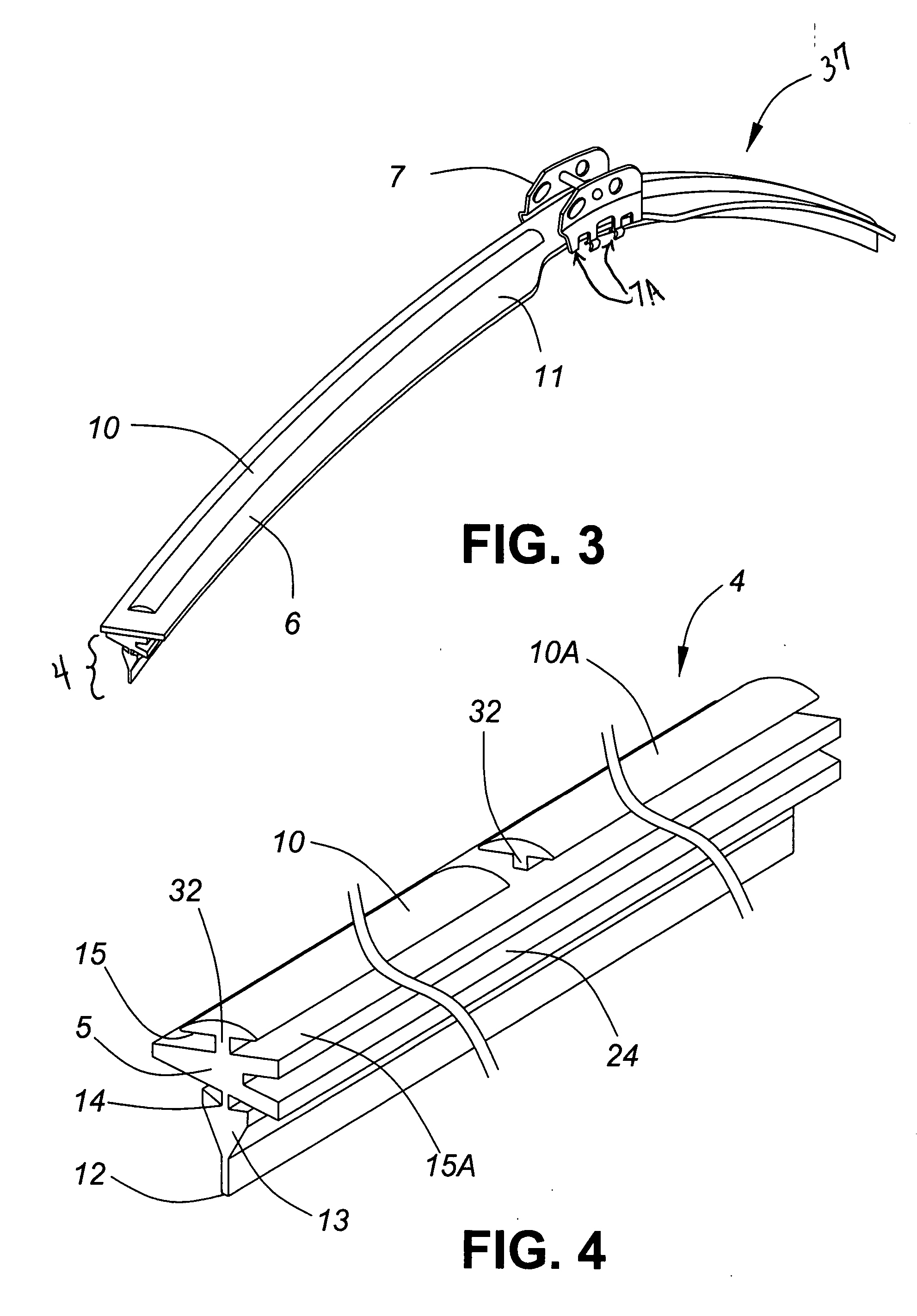
[0094] In FIG. 3, one view of the wiper blade assembly 37 is shown. The top surface or capping strip portion 10 of the wiper blade body 5 is shown protruding through the blade surface 6. The bottom portion 7A of the connector 7 is depicted engaging the narrowed portion of the stiffener 6 in the central region of the wiper blade 4. The stiffener 6 is provided with a winged portion 11 on one side which, beyond the narrowing in the center portion, tapers to a smaller width towards the respective outer ends of the wiper blade 4. The wiper blade 4 with the stiffener has a natural, unconstrained...


PUM


Abstract

A vehicle wiper blade and wiper blade assembly having a longitudinal stiffener mounted on the blade body at an offset angle from the central geometric plane of the blade edge, defined by the neck and wiping edge of the blade. When mounted in the presence of a wind stream flowing over the vehicular windshield, the protruding face surfaces of the stiffener function as an air dam to reduce lift-off effects, or as an airfoil to provide a supplemental pressure directing the wiper blade against the windshield. The proximity of the lower, forward edge of the blade to the windshield serves as an air dam. The upper trailing edge of the blade may be extended to serve as an airfoil. Torque about the wiping edge is avoided by directing the wiper arm pressing force in alignment with the central geometric plane of the blade, and preferably through the neck portion of the blade.

Description

[0001] This application is a Continuation-in-part of U.S. application Ser. No. 29 / 257,251, filed on Apr. 3, 2006, and claims priority to the Republic of Korea application 30-2005-0033448, filed Oct. 4, 2005, the disclosures of which are incorporated herein.FIELD OF THE INVENTION [0002] Embodiments of the invention relate to wiper blades for removing water from the windshields of vehicles. More particularly, the invention encompasses a wiper blade assembly designed to accommodate a high-speed airflow over a vehicle windscreen. BACKGROUND OF THE INVENTION [0003] An automotive windshield wiper removes water from a car windshield. It is operated by a wiper motor and mechanical linkages that move a wiper arm back and forth in a predetermined arc. At its end, the wiper arm carries a wiper blade. Along a portion of the arc, when the wiper blade is elevated and generally in line with the direction of airflow passing over the windshield, the airflow has a reduced tendency to lift the blade o...

Claims


Application Information

Patent Timeline
Patent Type & Authority Applications(United States)
IPC IPC(8): B60S1/40B60S1/38
CPCB60S1/3808B60S1/3848B60S2001/382B60S2001/3812B60S1/3879
Inventor KIM, IN KYUKIM, KYUNG SUKIM, TAE YOUNGNAM, KYUNG JONGKIM, HWA SEONG
Owner ADM21 CO LTD
Why Eureka
Try Eureka