Dynamoelectric rotor

Inactive Publication Date: 2007-11-22
MITSUBISHI ELECTRIC CORP
View PDF4 Cites 11 Cited by
  • Summary
  • Abstract
  • Description
  • Claims
  • Application Information

AI Technical Summary

Benefits of technology

[0011]The present invention aims to solve the above problems and an object of the present invention is to provide a dynamoelectric rotor that ena

Problems solved by technology

If this force is great, the field coil may rotate relative to the boss portion, giving rise to misalignments.
When misalignments of this kind occur, there is a risk that conducting wires that connect the field coil and slip rings that rotate together with the boss portion may break.
When these conducting wires break, changes in magnetic flux no longer occur in the armat

Method used


Image

  • Dynamoelectric rotor
  • Dynamoelectric rotor
  • Dynamoelectric rotor

Examples


Example

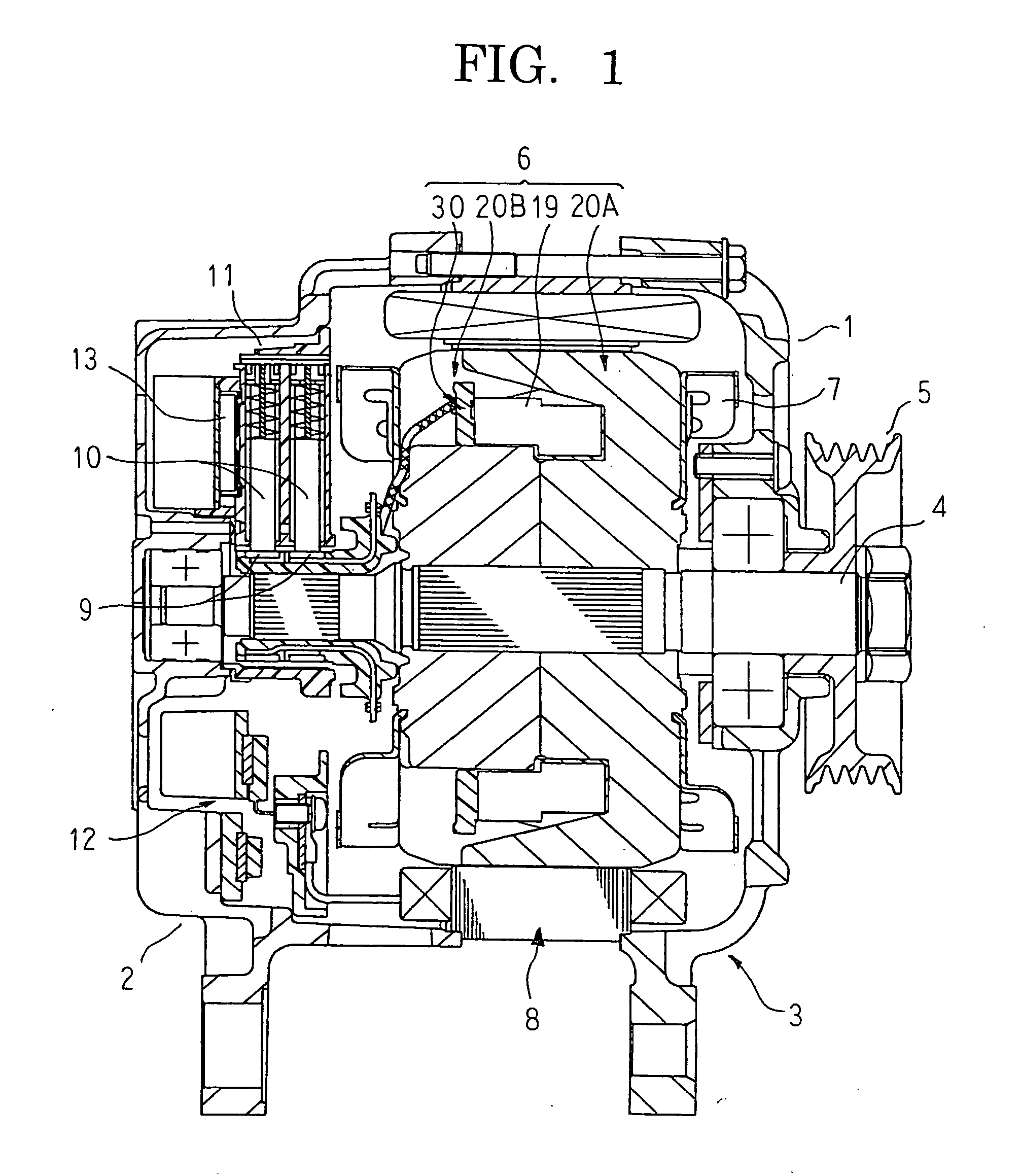
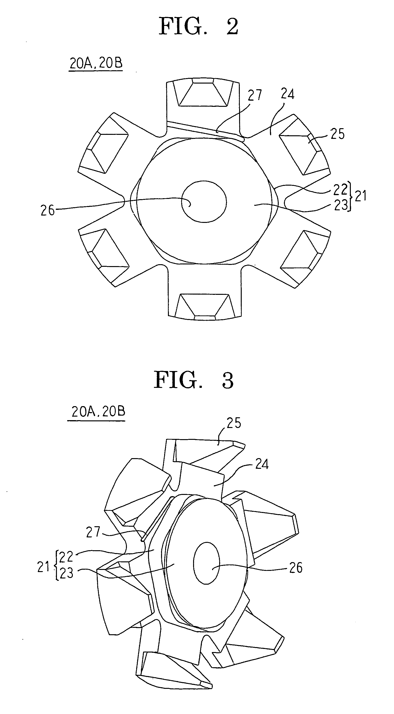
[0028]FIG. 1 is a longitudinal section of an automotive alternator according to Embodiment 1 of the present invention, FIG. 2 is a front elevation of a divided pole core in an automotive alternator rotor according to Embodiment 1 of the present invention, FIG. 3 is a perspective of the divided pole core in the automotive alternator rotor according to Embodiment 1 of the present invention, FIG. 4 is a front elevation of a bobbin in the automotive alternator rotor according to Embodiment 1 of the present invention, FIG. 5 is a longitudinal section of the automotive alternator rotor according to Embodiment 1 of the present invention, FIG. 6 is a front elevation that shows a state in which the bobbin is mounted to the divided pole core in the automotive alternator rotor according to Embodiment 1 of the present invention, and FIG. 7 is a front elevation that shows a state in which a field core is mounted to the divided pole core in the automotive alternator rotor according to Embodiment ...

Example

Embodiment 2

[0084]FIG. 11 is a perspective of a divided pole core in an automotive alternator rotor according to Embodiment 2 of the present invention.

[0085]In FIG. 11, an abutted portion 23A of a boss portion 21A is formed so as to have a dodecagonal cross-sectional shape in which spacing between sides that face each other (opposite sides) is made equal to that of the coil mount portions 22. Centers of the respective sides of the abutted portions 23A are formed so as to be aligned with centers and corner portions of respective sides of a coil mount portion 22 that has a hexagonal cross section.

[0086]Moreover, the rest of this embodiment is configured in a similar manner to Embodiment 1 above.

[0087]In Embodiment 2, because the abutted portions 23A of first and second pole cores 20A1 and 20B1 are formed so as to have an identical dodecagonal cross-sectional shape, the abutted portions 23A can be abutted with abutted surfaces aligned when the first and second pole cores 20A1 and 20B1 ...

Example

Embodiment 3

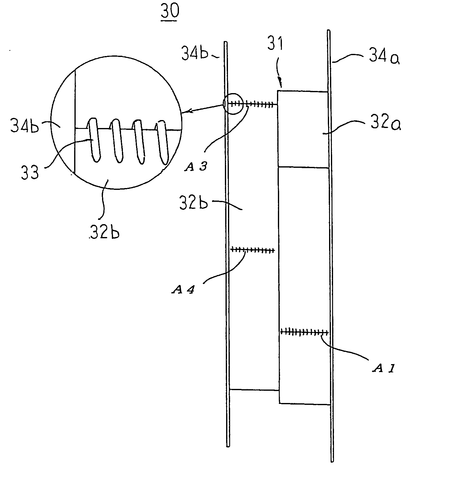
[0089]FIG. 12 is a developed projection of a drum portion of a bobbin in an automotive alternator rotor according to Embodiment 3 of the present invention.

[0090]In FIG. 12, first coil guide portions 33A1 are arrayed at a pitch of a coil thickness (d) axially on a side surface of a first tube body 32a that is positioned rearward in a direction of coil winding from a first corner portion A1 in close proximity to the first corner portion A1. Second coil guide portions 33A2 are similarly arrayed at a pitch of a coil thickness (d) axially on a side surface of the first tube body 32a that is positioned forward in a direction of coil winding from the first corner portion A1 in close proximity to the first corner portion A1 so as to be offset by half a coil thickness (d / 2) axially relative to the first coil guide portions 33A1.

[0091]Third coil guide portions 33A3 are arrayed at a pitch of a coil thickness (d) axially on a side surface of the first tube body 32a that is positione...


PUM


Abstract

Each of first and second pole cores has a boss portion, six core flange portions; and six claw-shaped magnetic pole portions, the first and second pole cores being disposed such that the claw-shaped magnetic pole portions face each other so as to intermesh and leading end surfaces of the boss portions are abutted with each other. The boss portions include coil mount portions in which cross-sectional shapes that are perpendicular to the central axis are hexagons; and abutted portions that have circular cross sections and that are disposed so as to protrude from leading ends of the coil mount portions. Radially-inner surfaces of the claw-shaped magnetic pole portions face side surfaces of the coil mount portions and are parallel to the side surfaces of the coil mount portions at the cross sections that are perpendicular to the central axis.

Description

BACKGROUND OF THE INVENTION[0001]1. Field of the Invention[0002]The present invention relates to a dynamoelectric rotor that is mounted to a vehicle such as a passenger car, or a truck, etc., for example.[0003]2. Description of the Related Art[0004]In conventional automotive alternator rotors, a field coil is wound onto a cylindrical boss portion. Thus, if the rotational acceleration changes greatly, a force acts that rotates the field coil relative to the boss portion due to inertia of the field coil. If this force is great, the field coil may rotate relative to the boss portion, giving rise to misalignments. When misalignments of this kind occur, there is a risk that conducting wires that connect the field coil and slip rings that rotate together with the boss portion may break. When these conducting wires break, changes in magnetic flux no longer occur in the armature, and function as an alternator can no longer be achieved.[0005]In view of these conditions, various rotors have b...

Claims


Application Information

Patent Timeline
IPC IPC(8): H02K3/00H02K1/22
CPCH02K1/243
Inventor NISHIMURA, SHINJI
Owner MITSUBISHI ELECTRIC CORP
Why Eureka
Try Eureka