Unlock instant, AI-driven research and patent intelligence for your innovation.

Systems and methods for improved control of micro-electrical-mechanical system (MEMS) electrostatic actuator

Inactive Publication Date: 2007-11-22
BOARD OF RGT THE UNIV OF TEXAS SYST
View PDF15 Cites 11 Cited by
  • Summary
  • Abstract
  • Description
  • Claims
  • Application Information

AI Technical Summary

Benefits of technology

[0009]The present disclosure provides, amongst other things, techniques to minimize or substantially eliminate lateral motion. In one respect, lateral motion in a comb drive actuated MEMS device is sensed and a value corresponding to the lateral motion is provided to a feedback controller

Problems solved by technology

The main issue of the comb drive design is achieving large deflections while minimizing the actuation voltage, resulting in a small deflection-to-size ratio of the actuator.
However, comb drives inherently suffer from an electromechanical instability called side pull-in or lateral instability, as illustrated in FIG. 1A.
Lateral instability occurs when the electrostatic stiffness transverse to the axial direction of motion exceeds the transverse mechanical stiffness of the suspension.
Additionally, although the comb structure is fabricated to be perfectly symmetrical, the comb structure is always unbalanced, causing the neighboring electrodes to contact each other when the voltage-deflection conditions are favorable.
Weak suspensions and large forces, designed to achieve large traveling ranges, increase the lateral instability.
Unfortunately, current suspension stiffening techniques limit the traveling range of the actuator.
These thicker structures can provide larger vertical electrode areas and substantially higher stiffness, but do not improve the limited deflection of comb drive structures.
The shortcoming of conventional methodologies are not intended to be exhaustive, but rather are among many that tend to impair the effectiveness of previously known techniques concerning MEMS actuators.
Other noteworthy problems may also exist, however, those mentioned here are sufficient to demonstrate the methodologies appearing in the art have not been altogether satisfactory and that a significant need exists for the techniques described and claimed in this disclosure.

Method used


Image

  • Systems and methods for improved control of micro-electrical-mechanical system (MEMS) electrostatic actuator
  • Systems and methods for improved control of micro-electrical-mechanical system (MEMS) electrostatic actuator
  • Systems and methods for improved control of micro-electrical-mechanical system (MEMS) electrostatic actuator

Examples


Embodiment Construction

[0026]The disclosure and the various features and advantageous details are explained more fully with reference to the nonlimiting embodiments that are illustrated in the accompanying drawings and detailed in the following description. Descriptions of well known starting materials, processing techniques, components, and equipment are omitted so as not to unnecessarily obscure the invention in detail. It should be understood, however, that the detailed description and the specific examples, while indicating embodiments of the invention, are given by way of illustration only and not by way of limitation. Various substitutions, modifications, additions, and / or rearrangements within the spirit and / or scope of the underlying inventive concept will become apparent to those of ordinary skill in the art from this disclosure.

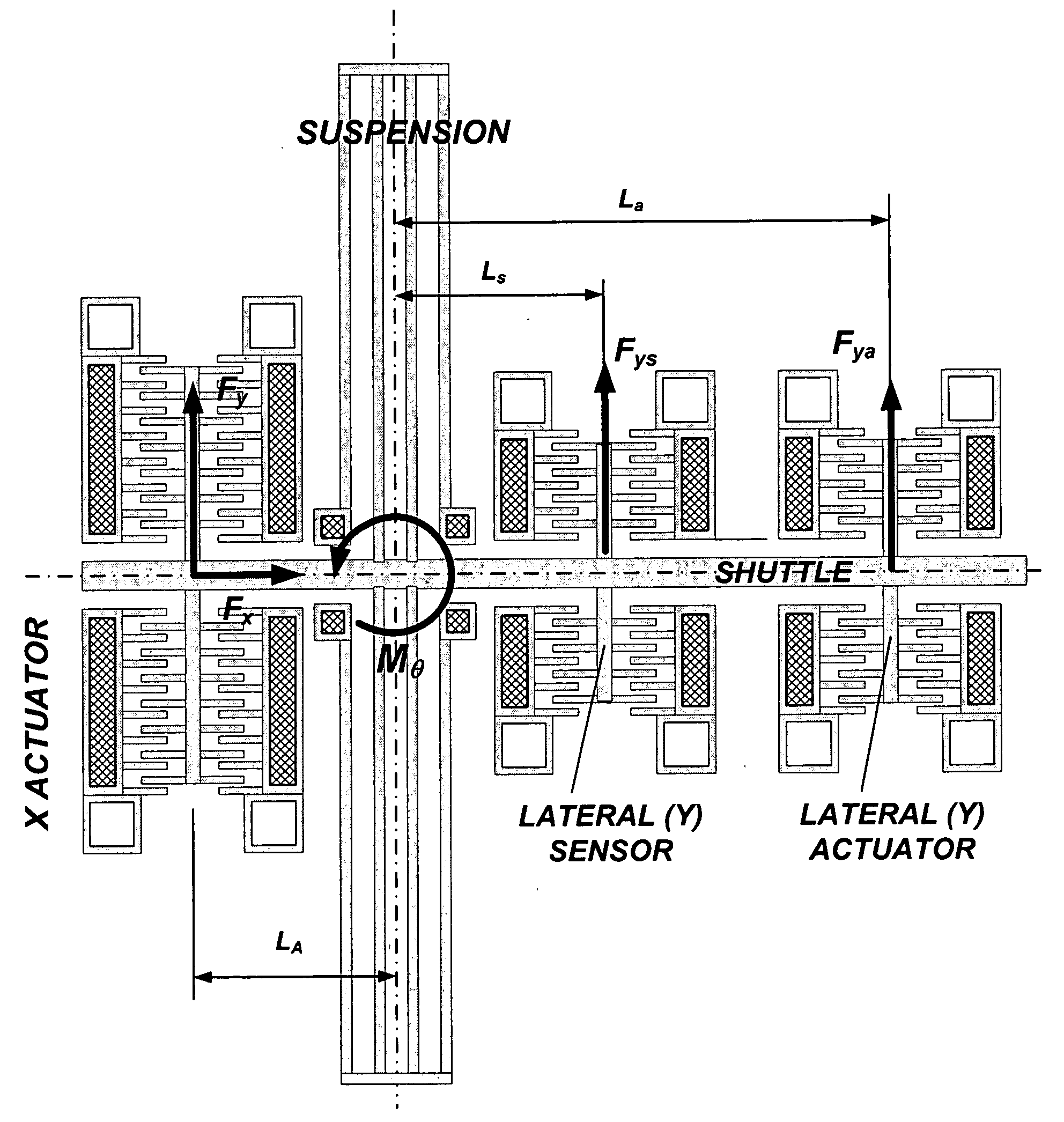
[0027]The present disclosure provides modeling of a comb actuator and using feedback control to manage axial and lateral motion. In one respect, a novel comb actuator str...


PUM


Abstract

Methods and apparatuses for sensing and adjusting lateral motion in a comb drive actuated MEMS device are provided. If lateral motion is sensed by a lateral motion sensor coupled to the comb drive actuated MEMS device, and the lateral motion is greater than a reference value, a feedback controller adjusts the lateral motion by providing a drive signal to a comb drive electrode of a comb drive actuator.

Description

STATEMENT AS TO RIGHTS TO INVENTIONS MADE UNDER FEDERALLY-SPONSORED RESEARCH AND DEVELOPMENT[0001]Aspects of this invention were made with government support of the Army Research Office, grant numbers DAAD19-02-1-0366 and National Science Foundation GOALI BES 0201773. Accordingly, the government may have certain rights in this invention.BACKGROUND OF THE INVENTION[0002]1. Field of the Invention[0003]The present invention relates generally to Micro-Electrical-Mechanical System (MEMS) technology. More particularly, it concerns improving the useful traveling range of MEMS actuators.[0004]2. Description of Related Art[0005]Micro-electrical-mechanical systems (MEMS) often use actuators to impart motion to, for example, positioning optical devices and switches and for turning gears. Electrostatic actuators are one of several types of actuators used in MEMS, including magnetic piezoelectric, thermal, and optical actuators. When compared to other micro actuators, electrostatic actuators gen...

Claims


Application Information

Patent Timeline
IPC IPC(8): H02N1/00
CPCH02N1/008H02K2201/18
Inventor BOROVIC, BRUNOLEWIS, FRANK L.LIU, AI QUNPOPA, DAN O.
Owner BOARD OF RGT THE UNIV OF TEXAS SYST