Optical module, electronic device, food analyzer, spectroscopic camera, driving method of wavelength variable interference filter

a technology of optical modules and optical filters, applied in optical radiation measurement, interferometric spectrometry, instruments, etc., can solve the problems of nonlinear change of the inability to perform suitable control, and different sensitivity of the electrostatic actuator, so as to reduce the sensitivity at the time of voltage applying, accurately extract the gap amount, and the effect of high accuracy

Active Publication Date: 2013-11-21
SEIKO EPSON CORP
View PDF4 Cites 27 Cited by
  • Summary
  • Abstract
  • Description
  • Claims
  • Application Information

AI Technical Summary

Benefits of technology

[0055]In this configuration, in the state where the bias voltage is applied to the first electrostatic actuator by the applying the bias voltage, the detecting of the amount of the gap between the reflection films is performed, and the feedback voltage corresponding to the gap amount detected by the detecting is applied to the second electrostatic actuator by the applying the feedback voltage. Thereby, in the application of the feedback voltage, the change of the sensitivity at the time of the voltage applying can be decreased. Thereby, the fine adjustment of a highly accurate gap amount can be performed with respect to a wide gap range, and the light of the target wavelength can be accurately extracted from the wavelength variable interference filter.

Problems solved by technology

However, in the electrostatic actuator, a displacement amount (sensitivity) of an interelectrode gap with respect to the applied voltage is nonlinearly changed according to the amount of the interelectrode gap.
Therefore, even when a gain of the control circuit which controls the voltage of the electrostatic actuator is optimally set to the sensitivity of a certain interelectrode gap, if the interelectrode gap is greatly changed, the sensitivity of the electrostatic actuator is different, and thus, a suitable control cannot be performed.
That is, there is a problem in that the control circuit functions according to the gain in which the interelectrode gap is set to only the case of the limited narrow range.
However, in this case, there is a problem that the system for realizing the variable gain is complicated.
Thereby, a bit number of the D / A converter increases, and thus, the costs increase.
However, in this case, when the set width of the target gap amount which can be set is a wide range, the data amount is increased, and thus, it is considered that a large capacity of memory is needed to store the data.
Therefore, when the second electrostatic actuator is disposed near the first capacitance detection electrode or the second capacitance detection electrode, crosstalk may occur, and thus, there is a concern that gap detection accuracy may be decreased due to the gap detection unit.
However, if the noise is increased, the control of the feedback voltage with respect to the second electrostatic actuator is not fully performed, and thus, it is also considered that the amount of the gap between the reflection films is slightly changed.

Method used


Image

  • Optical module, electronic device, food analyzer, spectroscopic camera, driving method of wavelength variable interference filter
  • Optical module, electronic device, food analyzer, spectroscopic camera, driving method of wavelength variable interference filter
  • Optical module, electronic device, food analyzer, spectroscopic camera, driving method of wavelength variable interference filter

Examples


first embodiment

[0072]Hereinafter, a first embodiment according to the invention will be described with reference to the drawings.

Configuration of Spectroscopic Measurement Device

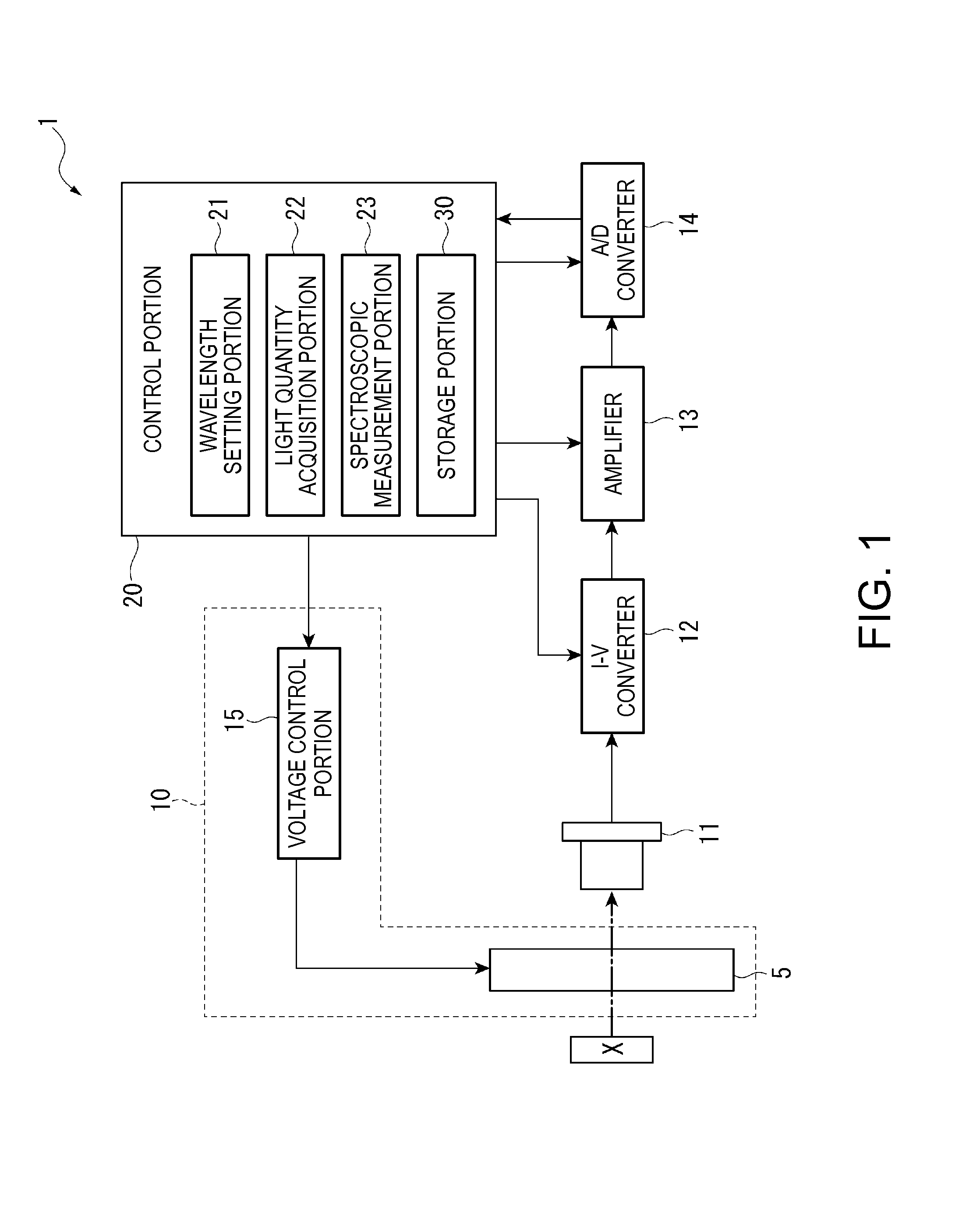
[0073]FIG. 1 is a block diagram showing a schematic configuration of a spectroscopic measurement device of the first embodiment according to the invention.

[0074]A spectroscopic measurement device 1 is an example of an electronic device of the invention, and is a device which analyzes light intensity having a predetermined wavelength in light to be measured which is reflected by an object to be measured X and measures an optical spectrum. Moreover, in the embodiment, the example is described in which the light to be measured which is reflected by the object to be measured X is measured. However, for example, when a light-emitting body such as a liquid crystal panel is used as the object to be measured X, the light which is emitted from the light-emitting body may be the light to be measured.

[0075]As shown in FIG. 1, the spe...

second embodiment

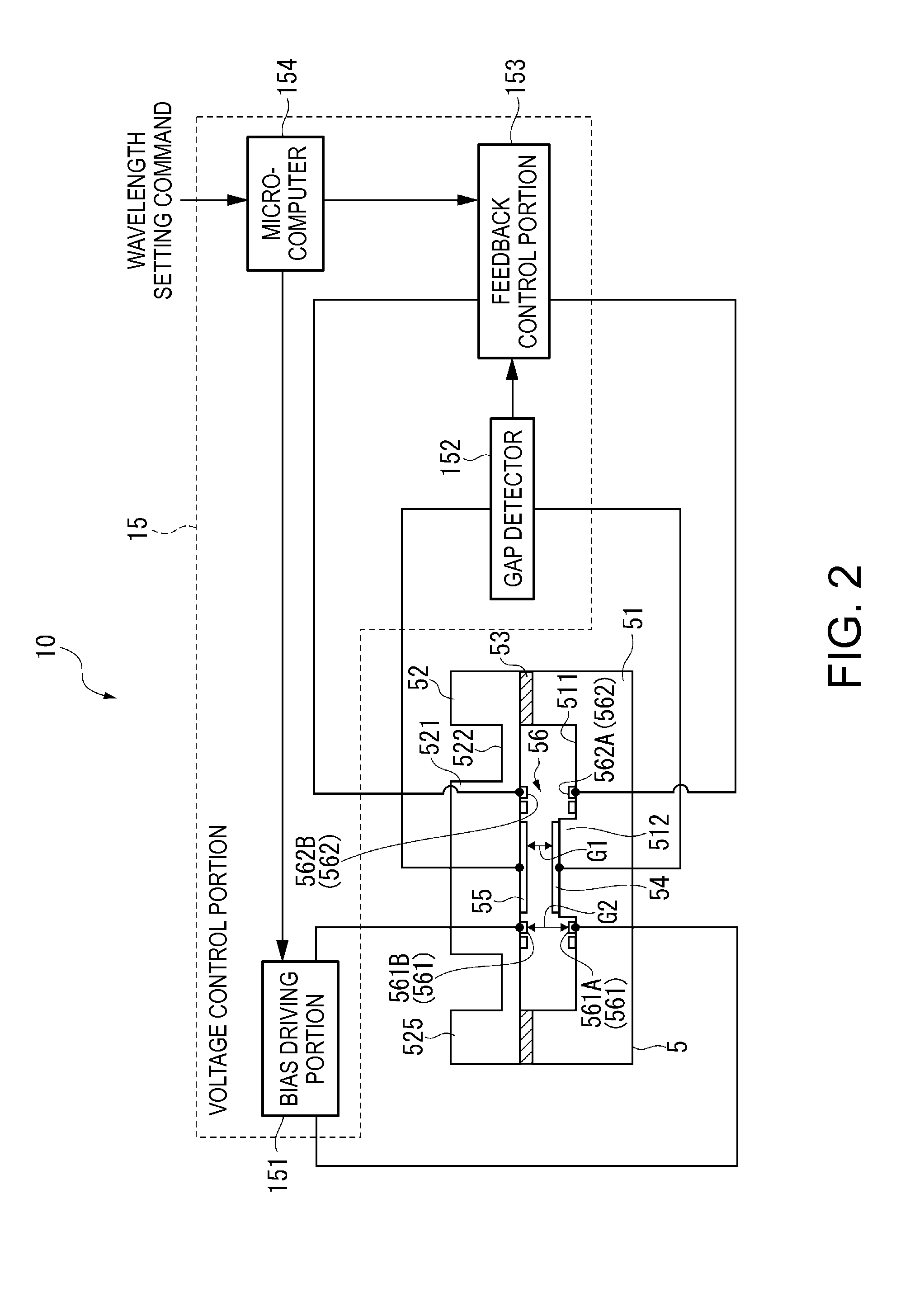
[0159]In the first embodiment, the feedback control portion 153 which includes the analog controller having a fixed gain is exemplified. On the other hand, a second embodiment is different from the first embodiment in that the feedback control portion 153 applies voltage (digital voltage in the embodiment) output by a digital controller to the second electrostatic actuator 562.

[0160]Moreover, since the second embodiment includes the similar configurations as the first embodiment, the feedback control portion 153 of the second embodiment will be described below with reference to FIG. 1, and descriptions of other configurations are omitted.

[0161]The feedback control portion 153 of the embodiment includes an A / D converter which converts voltage input from the gap detector 152 to digital signals (detection signals), a computing unit which calculates a feedback voltage value based on differences between detection signals and target detection signals, and a D / A converter which converts th...

third embodiment

[0164]In the first and second embodiments, examples are shown in which the fixed reflection film 54 and the movable reflection film 55 configure the first capacitance detection electrode and the second capacitance detection electrode according to the invention. On the other hand, a third embodiment is different from the first embodiment in that the electrodes which configure the first capacitance detection electrode and the second capacitance detection electrode are different from those of the first embodiment.

[0165]FIG. 10 is a plan view showing a schematic configuration of a wavelength variable interference filter 5A in the third embodiment.

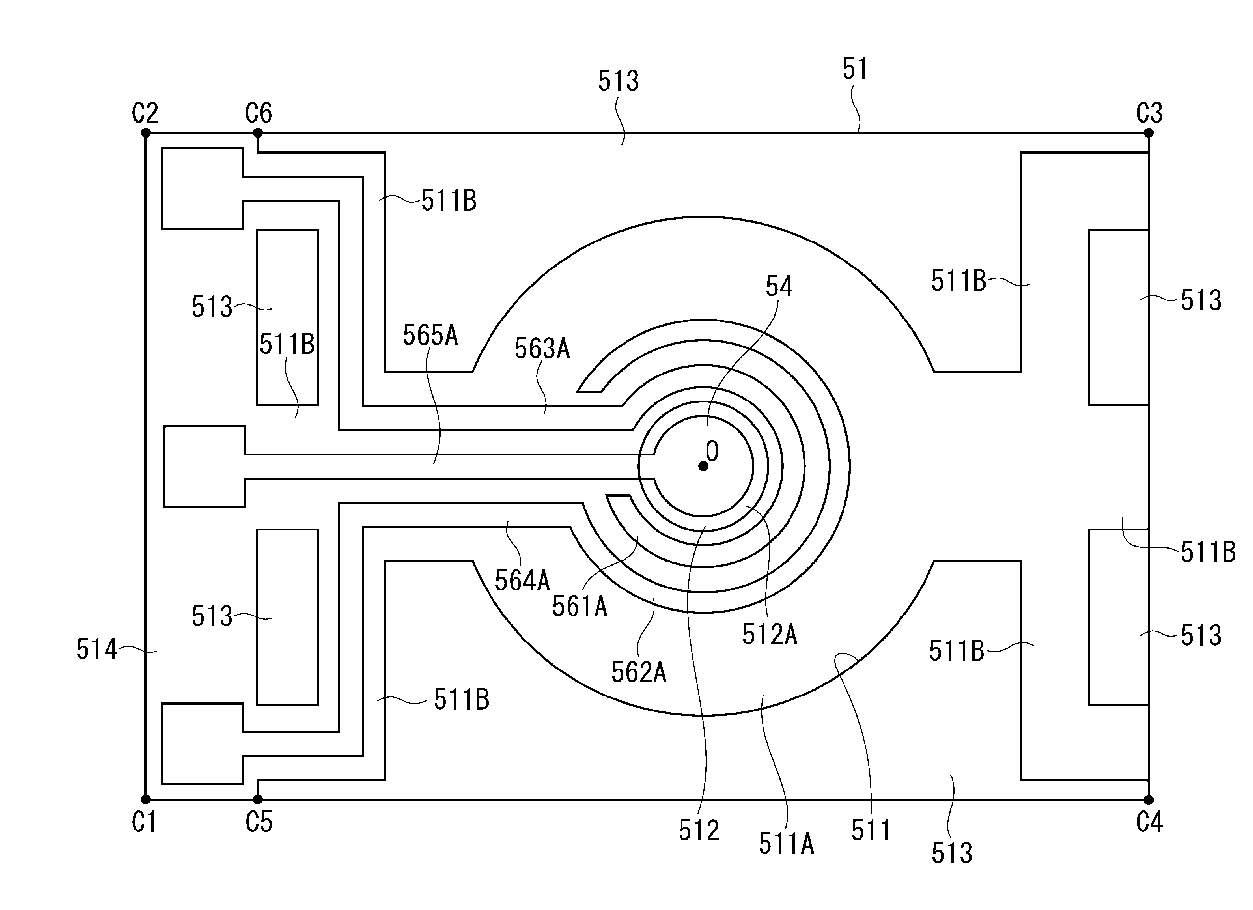
[0166]As shown in FIG. 10, in the wavelength variable interference filter 5A of the embodiment, the first electrode 561A and the second electrode 561B which configure the first electrostatic actuator 561 configure the first capacitance detection electrode and the second capacitance detection electrode according to the invention. In this case, t...


PUM


Abstract

A optical module includes, a wavelength variable interference filter which include reflection films opposite to each other and an electrostatic actuator portion including a first electrostatic actuator and a second electrostatic actuator and changing a gap between the reflection films, and a voltage control portion which controls voltage which is applied to the electrostatic actuator portion, the voltage control portion includes, a bias driving portion which applies bias voltage to the first electrostatic actuator, a gap detector, and a feedback control portion which applies feedback voltage corresponding to a detected gap amount to the second electrostatic actuator.

Description

BACKGROUND[0001]1. Technical Field[0002]The present invention relates to an optical module, an electronic device, a food analyzer, and a spectroscopic camera which include a wavelength variable interference filter, and a driving method of the wavelength variable interference filter.[0003]2. Related Art[0004]A known wavelength variable interference filter includes a pair of substrates that are opposite to each other, reflection films which are respectively disposed on each substrate so as to be opposite to each other, and electrodes which are respectively disposed on each substrate so as to be opposite to each other (for example, refer to JP-A-1-94312).[0005]In the wavelength variable interference filter disclosed in JP-A-1-94312, electrodes for a capacitance monitor which are opposite to each other and electrodes for applying an electrostatic force (electrostatic actuator) which are opposite to each other are disposed on each substrate. In the wavelength variable interference filter...

Claims


Application Information

Patent Timeline
Patent Type & Authority Applications(United States)
IPC IPC(8): G02B5/28G01J3/45
CPCG02B5/28G01J3/45G01J3/26G02B26/001
Inventor HIROKUBO, NOZOMU
Owner SEIKO EPSON CORP
Why Eureka
Try Eureka