Electrostatic actuator for microelectromechanical systems and methods of fabrication

a micro-electromechanical and actuator technology, applied in the field of electrostatic actuators, can solve the problems of cross-talk between adjacent actuators, difficult and costly construction, and more complex electronics to control actuators

Inactive Publication Date: 2006-08-29
CALIENT TECH
View PDF165 Cites 27 Cited by
  • Summary
  • Abstract
  • Description
  • Claims
  • Application Information

AI Technical Summary

Problems solved by technology

This may require more complex electronics to control the actuator that may be difficult and costly to build.
Also, the use of a large gap may result in cross-talk between adjacent actuators in an array.
Moreover, on the extremely small scale of these actuators, problems are introduced by the need to run conductors for the voltages very close together.
With higher voltages, interactions between conductors are har...

Method used


Image

  • Electrostatic actuator for microelectromechanical systems and methods of fabrication
  • Electrostatic actuator for microelectromechanical systems and methods of fabrication
  • Electrostatic actuator for microelectromechanical systems and methods of fabrication

Examples


Embodiment Construction

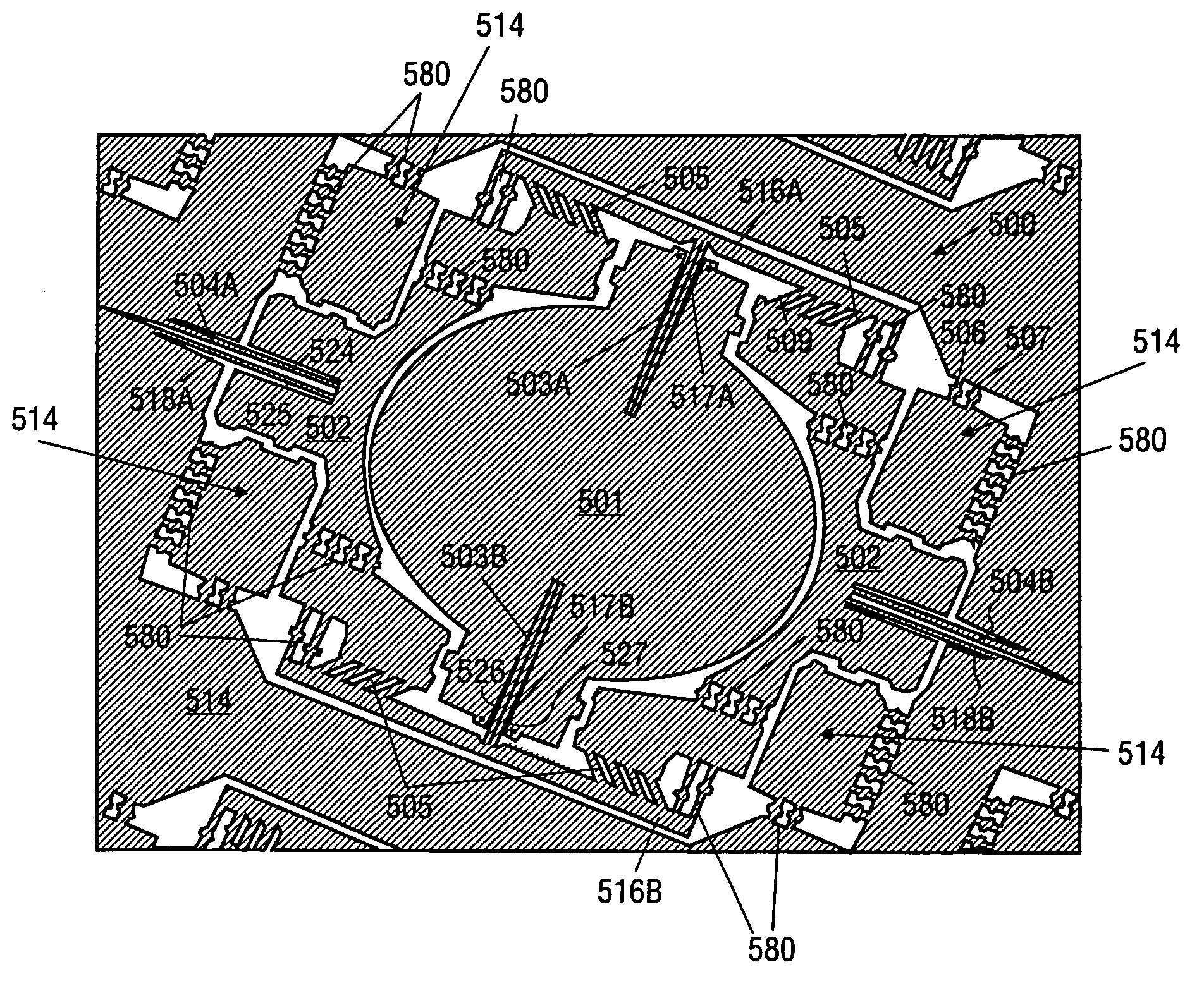
[0057]The method and apparatus described herein may be used to provide decoupled rotation of structures about different pivot points. For one embodiment, the apparatus may include one or more fixed blades mounted to a frame or substrate, one or more movable blades mounted to each structure to be moved, and flexures on which the structures are suspended. Separate movable blades are provided for each degree of freedom.

[0058]When voltage is applied between the fixed and movable blades, electrostatic attraction generates a force attracting movable blades toward blades that are fixed relative to the movable blades. The electrostatic attraction causes the structure to which the movable blade is mounted to rotate about the flexures. The angle of rotation that results may be related to the size of the blades, the number of blades, the spacing between blades, the stiffness of the flexures, and the magnitude of the voltage difference applied to the blades.

[0059]Methods of fabricating a microe...


PUM


Abstract

A method and apparatus are described that may be used to provide decoupled rotation of structures about different pivot points. The apparatus may include one or more fixed blades mounted to a frame or substrate, one or more movable blades mounted to each structure to be moved, and flexures on which the structures are suspended. Separate movable blades may be provided for each degree of freedom. When voltage is applied between the fixed and movable blades, the electrostatic attraction generates a force attracting movable blades toward blades that are fixed relative to the moveable blades, causing a structure to rotate about the flexures. The angle of rotation that results may be related to the size, number and spacing of the blades, the stiffness of the flexures and the magnitude of the voltage difference applied to the blades. The blades are fabricated using deep silicon etching.

Description

REFERENCE TO RELATED APPLICATIONS[0001]This application claims the benefit under 35 U.S.C. Section 119(e) of U.S. Provisional Application No. 60 / 179,912, filed Feb. 3, 2000, entitled Electrostatic Actuator for Micro Electro-Mechanical Systems With Method of Manufacture, and Product Using Same, and also claims priority from and is a divisional of U.S. patent application Ser. No. 09 / 775,491, filed Feb. 2, 2001.FIELD OF THE INVENTION[0002]This invention relates to the field of electrostatic actuators and, in particular, to microelectromechanical (MEM) electrostatic actuators.BACKGROUND[0003]Prior parallel-plate actuators, such as the example illustrated in FIGS. 1A (top view), 1B (side view), and 1C (side view), are typically designed with gaps 13 that are significantly larger than the stroke range of the actuator. When a voltage is applied between two electrode plates 15 and 10, an attractive force is produced between the electrode plates that rotates plate 10. Because the maximum rot...

Claims


Application Information

Patent Timeline
IPC IPC(8): H02N1/00G02B26/08G02B26/10H01H59/00H01H67/22
CPCH02N1/008H01H67/22H01H2001/0068
Inventor ADAMS, SCOTTDAVIS, TIMMILLER, SCOTTSHAW, KEVINCHONG, JOHN MATTHEWLEE, SEUNG CHRIS BOK
Owner CALIENT TECH
Why Eureka
Try Eureka