On-line portal system and method for management of devices and services

a technology of portal system and portal management, applied in the field of online portal system and method, can solve the problems of limited interoperability and adoption, excessive burden on the owner by the limitations of the use of their software, and owner being forced to buy a complete new system

Inactive Publication Date: 2007-11-22
VASEFI DARYUSH +1
View PDF5 Cites 140 Cited by
  • Summary
  • Abstract
  • Description
  • Claims
  • Application Information

AI Technical Summary

Benefits of technology

[0012]According to one aspect, a web-based device management and user access system is provided, which comprises a user interface or log-in module which allows a user to access the system, a surveillance unit which is linked to a plurality of surveillance devices associated with users of the system, at least some of the surveillance devices having different application programming interfaces, the surveillance unit having a communication module which communicates with each surveillance device using the application programming interface of the respective surveillance device, a control module which controls operation of each linked surveillance device to send data from the surveillance device to the surveillance unit, an archiving module which receives and stores data from each of the surveillance devices to which it is linked, a management module which monitors the status of each surveillance device and provides a notification to the respective user if a monitored surveillance device is not operating correctly, and a display module which displays the output of selected surveillance devices to the user associated with the devices on request by the user, the display module having a user control module which allows the user to select between different display options including real time and archived data display.
[0013]In one embodiment, the system has a data analysis or traffic count module which analyzes data collected by traffic count or motion detector devices in ways which are controlled by the registered user associated with the devices. One way in which the analytic module may be operated is to carry out a traffic count of any object specified by a user, for example the number of people passing through one or more locations in a facility (home or business) in selected time periods. The analytic module includes a display module for displaying analyzed data in various formats, such as graphical, numerical tables, and the like. The analytic module may be used, for example, to determine the effectiveness of an advertising campaign. Effectiveness may be gauged by an increase in traffic after the campaign is introduced. The analytic module may also be linked to point of sale (POS) systems at various businesses so as to record and store sales information. This in turn may be linked to the traffic data.
[0014]In one embodiment, additional functions may be provided by the management and user access system, such as a home or business automation system which has a connection module which connects to a plurality of home or business automation modules associated with users of the system, each automation module being linked to one or more devices in a home or office selected from the group consisting of lighting, appliances, irrigation devices, locking devices, utilities, computer systems, and entertainment systems, and a user control module which allows a user logged on to the system to control operation of the automation system. The system may also include a personal assistant module which allows a user to enter information on various types of item purchased, such as date of purchase, vendor, warranty and service information, and which tracks deadlines such as warranty expiry dates and sends reminders to users in advance of such dates.
[0015]Other features and advantages of the present invention will become more readily apparent to those of ordinary skill in the art after reviewing the following detailed description and accompanying drawings.

Problems solved by technology

One problem with current systems is that the manufacturers of equipment for such systems provide software which only works with their own hardware, so that end users are locked into using hardware which works only with one manufacturer's software or with one automation system.
Automation system and manufacturer software is typically based on one technology, such as Microsoft® operating systems, and this results in limited interoperability and adoption.
However, if another manufacturer comes up with a better camera having better resolution, or a less expensive camera, for example, the system owner cannot simply purchase one or more of those cameras and add them to the existing system, but is excessively encumbered by the limitations of what the manufacturer imposes by the use of their software.
In many instances the owner is forced to buy a complete new system or incur excessive integration costs.
Since technology in this area and others is progressing rapidly and prices are dropping considerably in a short time frame, the inability to add components from other manufacturers to an existing system causes inconvenience to customers.
Another problem with existing automated systems such as surveillance, security, automated control of various home or business systems, and the like, is that the owner has to learn a specific software with one system and this software may be completely different if they change to a different manufacturer's system, resulting in significant re-training of staff which can be expensive.
Also, individual system components are typically not monitored automatically for maintenance purposes, such as the cameras of surveillance or security systems.
Thus, when a camera or recording unit becomes inoperative, the owner often does not find out until a security event has happened, when it is too late.
Another problem with existing systems is that most have PC based software, which must be installed on a workstation by the user before the user can access or manage the device.
Similar issues exist in the home automation and control industry, where the end-user is locked by any software they purchase and the devices which are compatible with that software.

Method used


Image

  • On-line portal system and method for management of devices and services
  • On-line portal system and method for management of devices and services
  • On-line portal system and method for management of devices and services

Examples


Embodiment Construction

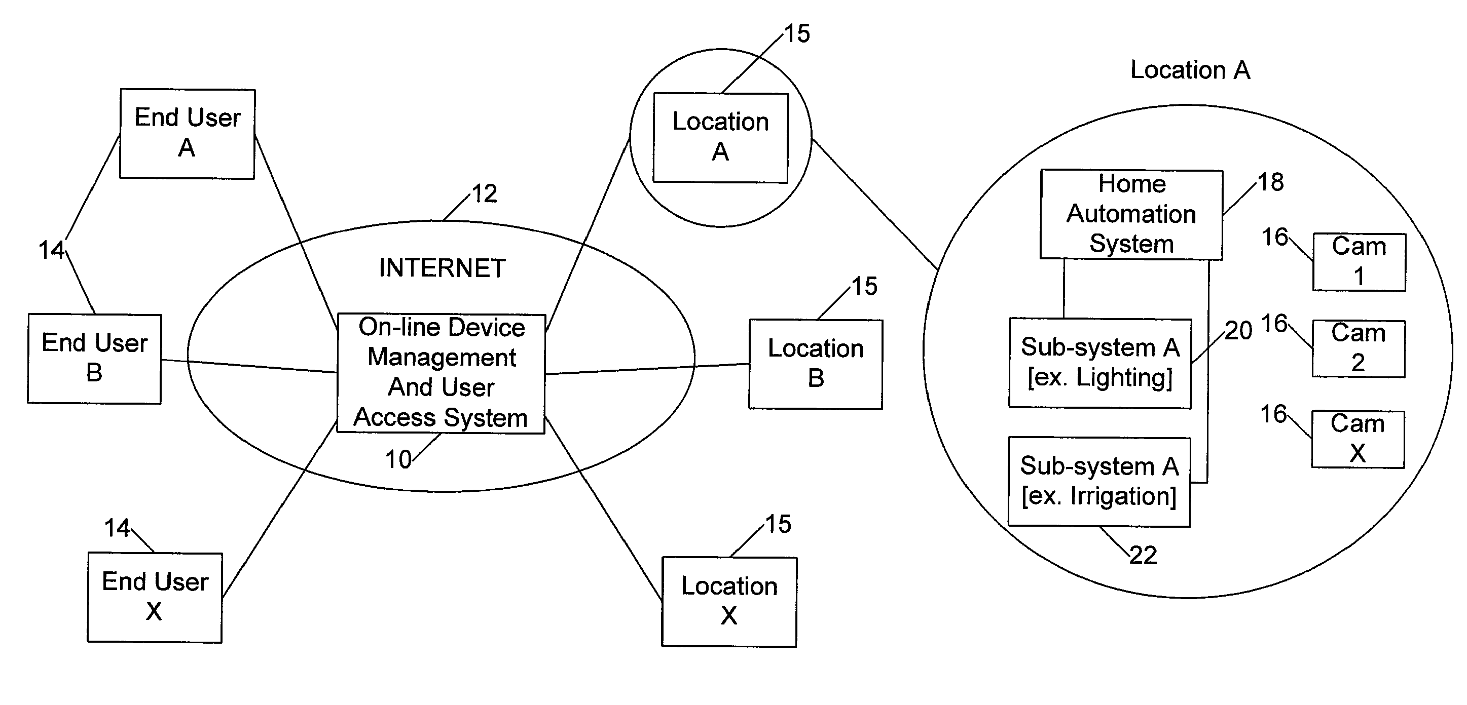
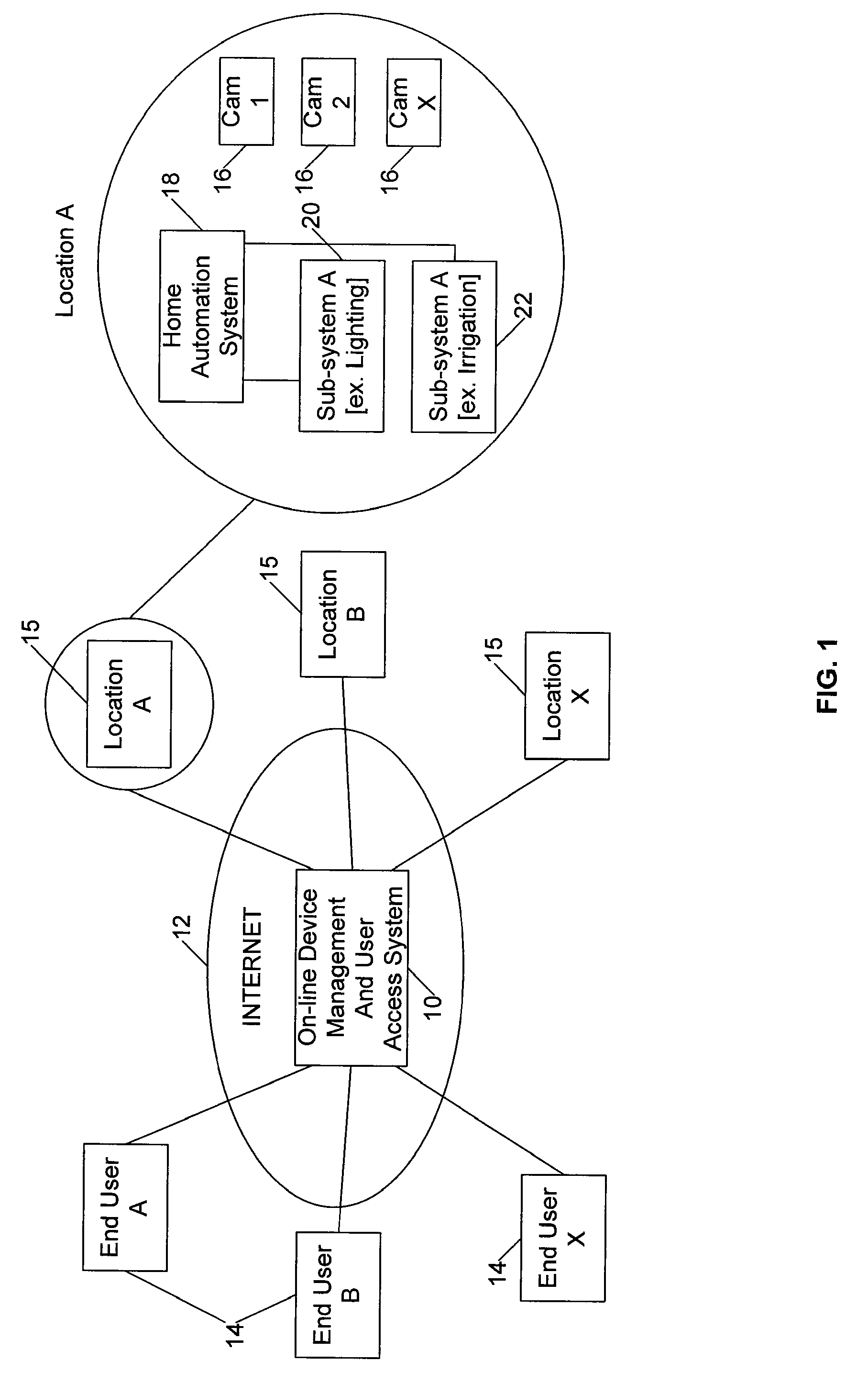
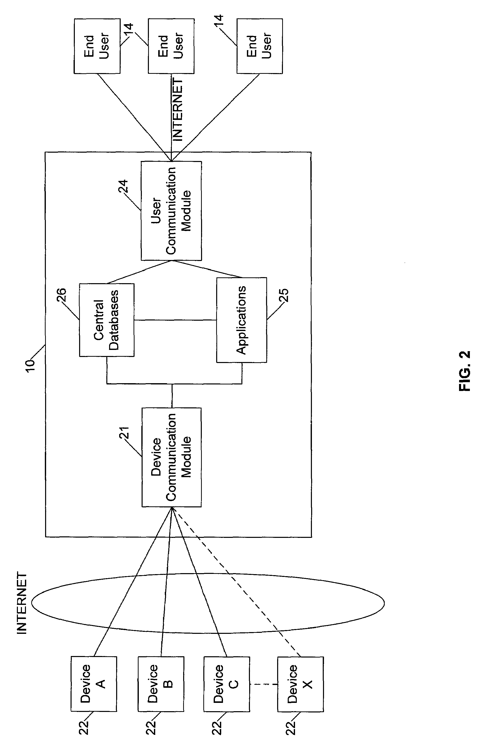
[0034]Certain embodiments as disclosed herein provide for systems and methods for providing on-line or web-based management of devices, services and / or systems. For example, one method as disclosed herein allows for users to monitor office or home systems such as surveillance and automation systems over an on-line portal accessible through the Internet or other public network, with the option to access other selected services through the same portal.

[0035]After reading this description it will become apparent to one skilled in the art how to implement the invention in various alternative embodiments and alternative applications. However, although various embodiments of the present invention will be described herein, it is understood that these embodiments are presented by way of example only, and not limitation. As such, this detailed description of various alternative embodiments should not be construed to limit the scope or breadth of the present invention as set forth in the appe...


PUM


Abstract

An on-line device management system provides a common interface for managing devices using a single login to a website associated with the system over a public network. Users sign up for selected services including surveillance and provide information on associated user devices which include devices with different operational programming interfaces, and user and device information is stored by the system. The system communicates with the devices and controls the devices using the stored device information so that the devices send data to the system on a selected schedule. The system creates a customized interface for each user through which the user can monitor and manage building surveillance devices from a remote location at any time.

Description

RELATED APPLICATION[0001]The present application claims the benefit of co-pending U.S. provisional patent application No. 60 / 801,572 filed May 18, 2006, the content of which is incorporated herein by reference in its entirety.BACKGROUND[0002]1. Field of the Invention[0003]The present invention generally relates to an on-line portal system and method for providing users with various services, and is particularly concerned with a system for providing on-line or web-based management of devices, digital services or systems associated with homes, businesses, and other such facilities.[0004]2. Related Art[0005]Various digital services and systems are currently provided to homeowners, businesses, and the like, such as security or surveillance systems, automation and control systems for utilities, energy management, irrigation, lighting, and the like. One problem with current systems is that the manufacturers of equipment for such systems provide software which only works with their own har...

Claims


Application Information

Patent Timeline
Patent Type & Authority Applications(United States)
IPC IPC(8): G08B29/00G06Q10/00H04Q7/38H04N7/18
CPCG06Q10/06G08B13/19656H04L67/025H04L12/2818H04N7/181G08B13/19682
Inventor VASEFI, DARYUSHMOSTAJAB, NAVIDEH
Owner VASEFI DARYUSH
Why Eureka
Try Eureka