
Method and apparatus for rendering a cell-based switch useful for frame based application protocols

a frame-based application and switch fabric technology, applied in the field of switch fabrics, can solve the problems of difficult to use cell-based switch fabrics for fibre channel and other similar protocols, undesirable latency, and difficult to use such switch fabrics

Inactive Publication Date: 2007-11-22
AVAGO TECH INT SALES PTE LTD +1
View PDF19 Cites 5 Cited by
  • Summary
  • Abstract
  • Description
  • Claims
  • Application Information

AI Technical Summary

Benefits of technology

[0019] In further accordance with the present invention, the number of valid bytes in each cell is calculated, and that number is placed within each cell at a fixed location. The EOP indicator is placed at a fixed location within each cell, and is asserted for the last cell of a packet, or for the cell following the last cell of a packet. The present method permits, inter alia, low-latency routing from FC-port to FC-port, and scalability from 32, up to even 512 2 Gbps FC ports. The capability for expansion is believed to be especially important in the case of storage area networks.

Problems solved by technology

While cell-based switches can be used successfully in WAN and ATM type of applications, use of such switch fabrics can be problematic when the same are connected to frame-based protocols such as Fibre Channel or other SAN applications.
If an entire FC frame is buffered to determine the frame (i.e., packet) length to insert into the first cell prior to transmission of the frame, the latency would be undesirable (for example ˜20 μs @1 Gbps).
Thus, it has been difficult to use cell-based switch fabrics for Fibre Channel and other similar protocols since the entire Ethernet frame must be received and buffered before segmentation may take place.
This creates problems when the two fabrics are utilized together.

Method used


Image

  • Method and apparatus for rendering a cell-based switch useful for frame based application protocols
  • Method and apparatus for rendering a cell-based switch useful for frame based application protocols
  • Method and apparatus for rendering a cell-based switch useful for frame based application protocols

Examples


Embodiment Construction

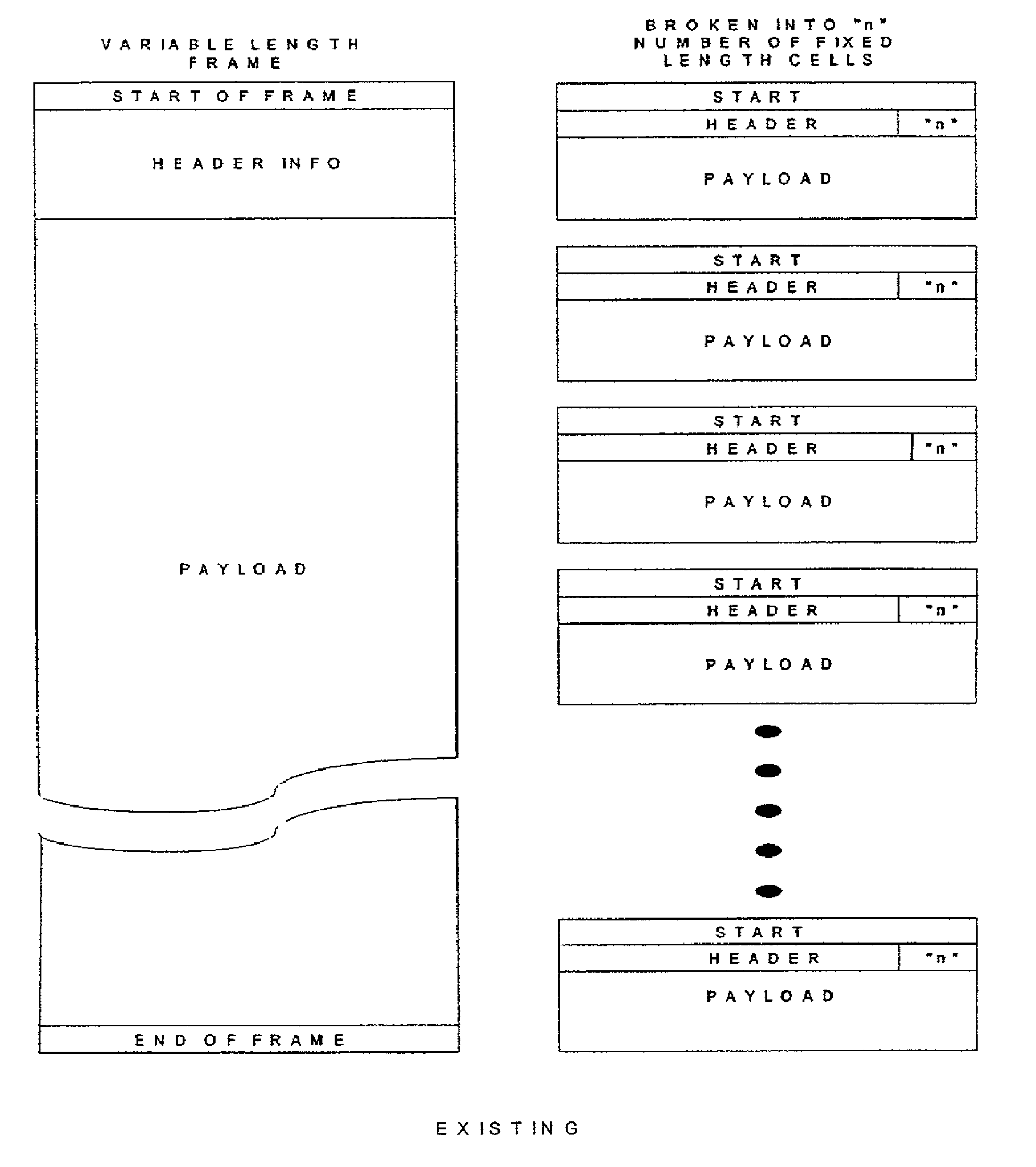
[0028] In accordance with the present invention, there is provided a method and associated apparatus for decomposing a packet into N single-cell packets, and programming the packet length for a maximum frame-based protocol (i.e., Fibre Channel) frame size, and using an “end of packet bit” (“EOP”) in the cell header to signal the end of the packet if it was shorter than the programmed length (“early packet termination”). It should be understood that other protocols, such as the asynchronous transfer mode (ATM) could be used without departing from the scope of the present invention. In a broad sense, the present invention provides that a packet is decomposed into N single-cell packets and the packet length is programmed for a maximum Fibre Channel frame size using an end of packet (EOP) bit in a cell header to signal the end of the packet if it was shorter than the programmed length (hereinafter referred to as “early packet termination”)

[0029] Existing methods for sending a collectio...


PUM


Abstract

A method for providing an early packet termination such that prior to the complete transmission of the number of cells specified in the first cell of a packet, a crossbar connection is released. The act of releasing the connection is triggered on recognition of an End of Packet bit (EOP) set in any cell of the stream. The feature can be enabled, for example, by a specific act of setting a register bit, connecting a pin to Vcc or ground or some other intentional act. The feature will default to the inactive state upon reset.

Description

[0001] This application is a continuation of U.S. patent application Ser. No.09 / 995,605, now U.S. Pat. No. 7,218,636, entitled “Method and Apparatus for Rendering a Cell-Based Switch Useful for Frame Based Application Protocols”, which claims priority of the provisional U.S. patent application having the same title, filed Jun. 13, 2001 and having Ser. No. 60 / 297,454, which is hereby incorporated by reference. This application is related to U.S. patent application Ser. No. 10 / 873,550, filed Jun. 21, 2004 (now U.S. Pat. No. 7,072,298) and entitled “Method and Apparatus for Rendering a Cell-Based Switch Useful for Frame Based Application Protocols” which was filed as a continuation in part of U.S. patent application Ser. No. 09 / 995,605. This application is also related to U.S. patent application Ser. No. 11 / 478,419 filed Jun. 28, 2006, which is a continuation of U.S. patent application Ser. No. 10 / 873,550 and has the same title. This application is also related to, and includes similar...

Claims


Application Information

Patent Timeline
Patent Type & Authority Applications(United States)
IPC IPC(8): H04L12/28H04L12/56H04Q11/04
CPCH04L12/5601H04L49/608H04Q11/0478H04L2012/5627H04L2012/5665H04L2012/5605
Inventor PAUL, HARRY V.BRANCO, RICHARDPEARSON, JERELD W.KOELLNER, GREGORY L.
Owner AVAGO TECH INT SALES PTE LTD
Learn More