
Packets transfer device that intelligently accounts for variable egress channel widths when scheduling use of dispatch bus by egressing packet streams

a packet transfer device and egress channel technology, applied in the field of telecommunication systems, can solve the problem that the conventional paradigm does not account for the possibility of variable bandwidth, and achieve the effect of efficient tailoring

Active Publication Date: 2007-11-22
MICROSEMI STORAGE SOLUTIONS US INC
View PDF4 Cites 55 Cited by
  • Summary
  • Abstract
  • Description
  • Claims
  • Application Information

AI Technical Summary

Benefits of technology

[0011]A packets transfer device in accordance with the present disclosure may be additionally configured to have data buffering FIFO's with programmably variable (elastic) FIFO depths for each of programmably re-configurable ports or communication channels so that FIFO depth may be efficiently tailored to match the bandwidth needs of differently configured ingress and / or egress channels.

Problems solved by technology

A conventional paradigm does not account for the possibility of variable bandwidths on the ingress and / or egress channels.

Method used


Image

  • Packets transfer device that intelligently accounts for variable egress channel widths when scheduling use of dispatch bus by egressing packet streams
  • Packets transfer device that intelligently accounts for variable egress channel widths when scheduling use of dispatch bus by egressing packet streams
  • Packets transfer device that intelligently accounts for variable egress channel widths when scheduling use of dispatch bus by egressing packet streams

Examples


Embodiment Construction

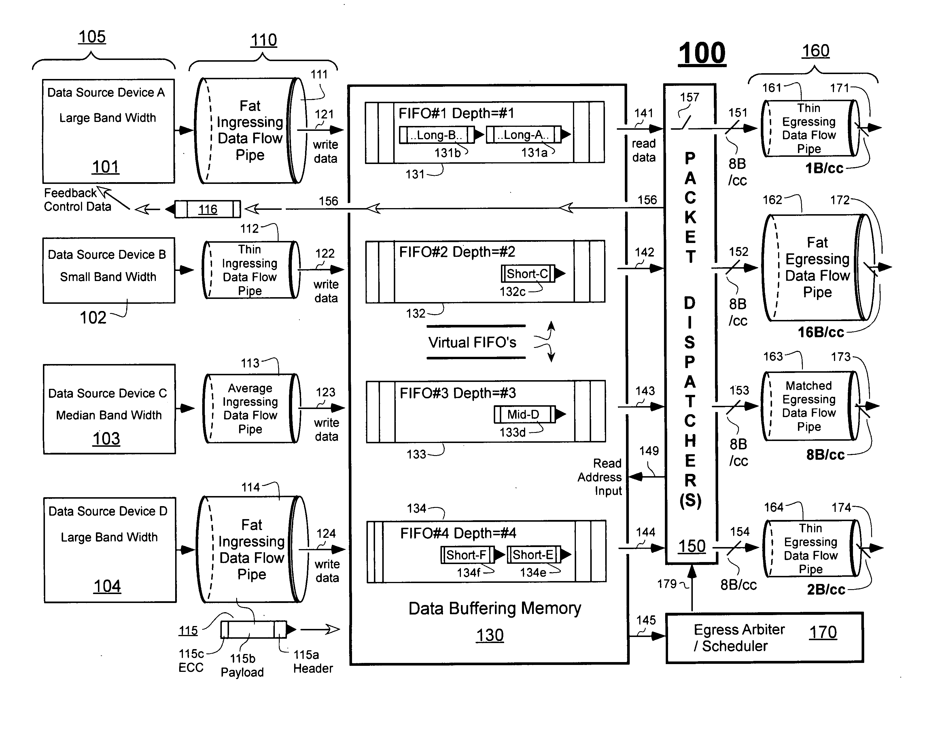
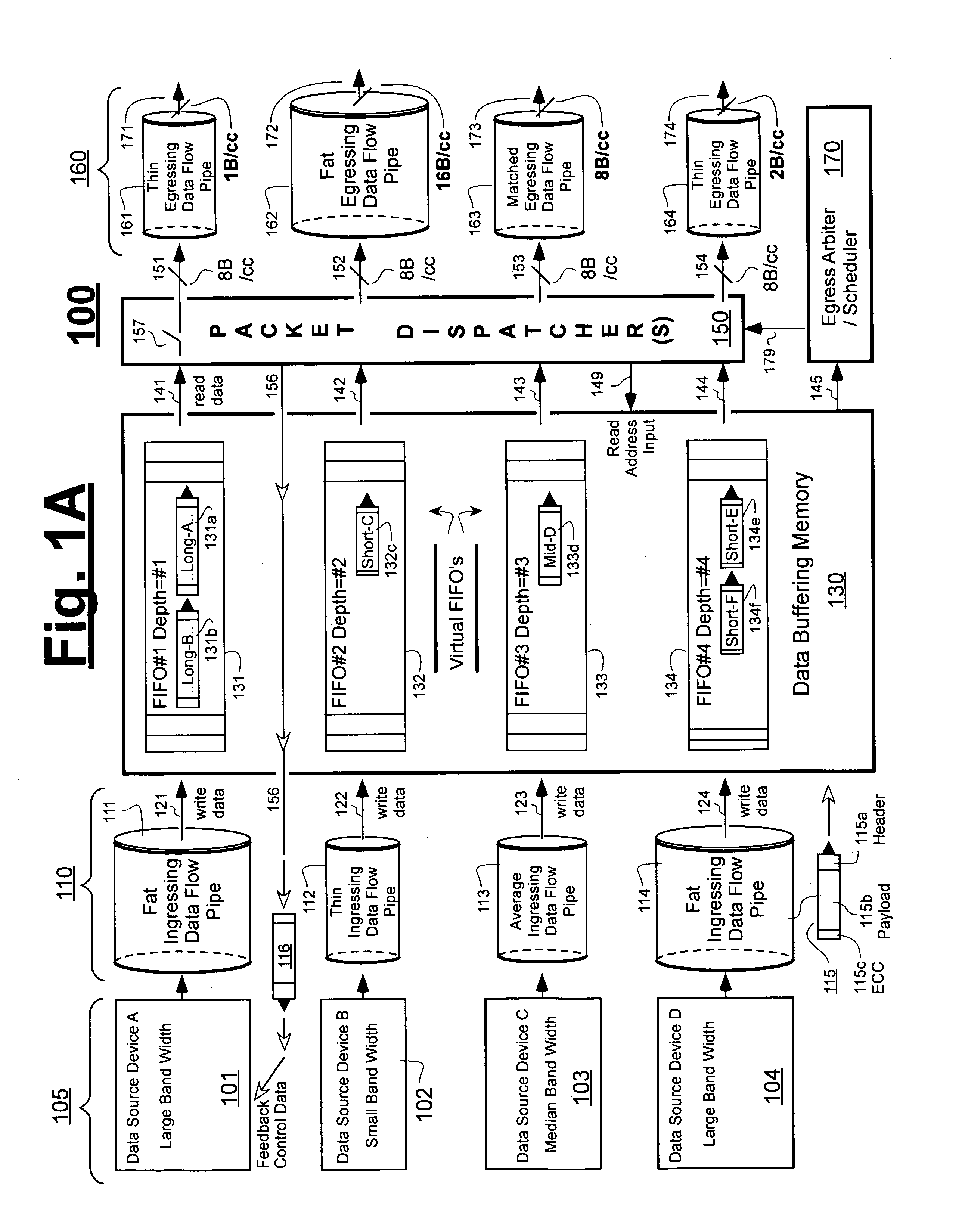
[0022]Referring to a hypothetical first telecommunication system 100 that is schematically illustrated in FIG. 1A, seen under column 105 are first through fourth data source devices, 101-104. Data source device “A” (101) is taken to have a relatively large data output bandwidth—at least for the moment—while device “B” (102) has a relatively small bandwidth and device “C” (103) has a median bandwidth. Device “D” (104) of the example is shown to have a relatively large bandwidth, like that of device “A”, although it could have instead been programmably or fixedly configured to have an output bandwidth value almost anywhere in the allowable spectrum of the system between what may be considered a very small bandwidth (system minimum) and very large bandwidth (system maximum). Specific bandwidth values may vary from application to application, or time to time. FIG. 1A is provided mostly for purpose of generically illustrating certain problems associated with telecommunication systems tha...


PUM


Abstract

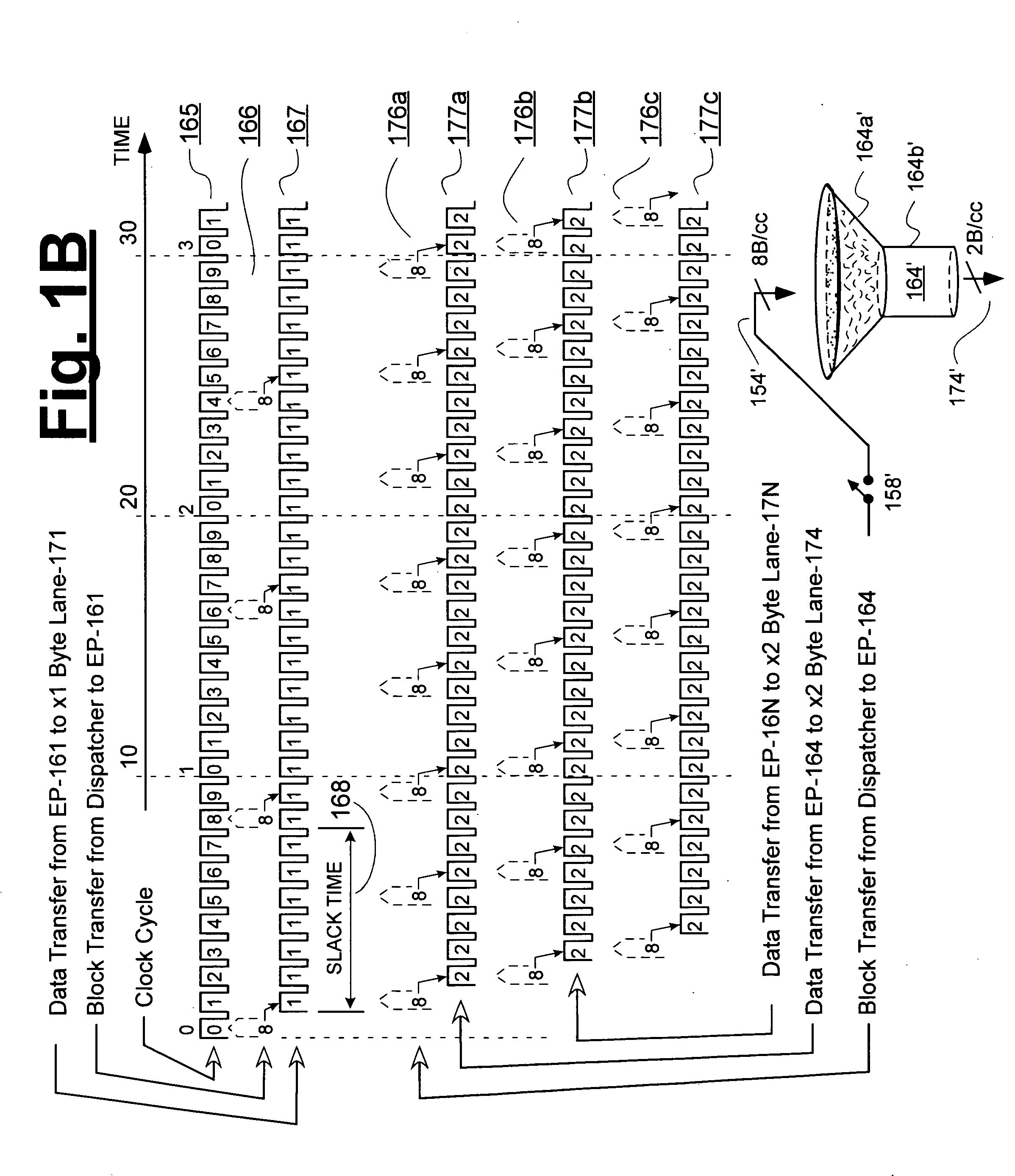
In PCI-Express and alike communications systems, data bandwidth per channel can vary as a result of negotiated port aggregation and / or bifurcation during network bring-up. Disclosed are systems and methods for opportunistically interleaving dispatches of packet data for secondary egress channels when the data bandwidth of a primary egress channel is relatively small and thus creates slack on a dispatch bus between dispatches of primary data blocks.

Description

CROSS REFERENCE TO CO-OWNED APPLICATION[0001]The following copending U.S. patent application is owned by the owner of the present application, and its disclosure is incorporated herein by reference:[0002](A) Ser. No. 11 / 390,754 [Attorney / Client Docket Nos.: M-16365, idt-2013] filed Mar. 28, 2006 by Nadim Shaikli and originally entitled, “Packets Transfer Device Having Data Absorbing Buffers with Elastic Buffer Capacities”.FIELD OF DISCLOSURE[0003]The present disclosure of invention relates generally to telecommunication systems that transmit information in packet format. The disclosure relates more specifically to systems that can employ ingress and egress flow rates of differing values for different communication channels.DESCRIPTION OF RELATED ART[0004]The use of digitally-encoded packets in telecommunication systems is well known. Typically each packet is layered like an onion to have header-type outer shell sections, a payload core section and one or more error correction sectio...

Claims


Application Information

Patent Timeline
Patent Type & Authority Applications(United States)
IPC IPC(8): H04L12/56H04J3/22
CPCH04J3/047H04L47/6215H04L47/10H04L12/5693H04L47/50
Inventor SHAIKLI, NADIM
Owner MICROSEMI STORAGE SOLUTIONS US INC
Learn More