Robust fluid flow and property microsensor made of optimal material

Inactive Publication Date: 2006-09-19
HONEYWELL INT INC
View PDF22 Cites 10 Cited by
  • Summary
  • Abstract
  • Description
  • Claims
  • Application Information

AI Technical Summary

Benefits of technology

[0018]Recent developments in glass materials, including photosensitive glass and pyrex, have shown that micromachining is possible and extremely effective. Consequently, this material can now provide an alternate die substrate for a micromachined flow and property sensor. The present invention exploits the characteristics of glass (photosensitive glass, fused silica, etc.) or alumina materials to produce a flow and property sensor with optimized physical characteristics. Providing a glass based sensor in a Microbrick™ or microfill structure consequently enables the fabrication of a rugged sensor for sensing liquid properties or high mass flux fluid flow, without pressure-stress-induced error signals.
[0019]Due to the recent developments in glass, the use of this material as a die substrate generally reduces the amount of structural machining necessary. More specifically, the substrate can now be fabricated in a Microbrick™ or microfill structure which has a substantially solid structure. In this type of sensor die, the heating and sensing elements are placed directly on the

Problems solved by technology

However, due to the open nature of the microbridge structure, condensates from vapor can be uncontrollably retained in the microbridge structure leading to uncontrolled changes in its thermal response, or output, making the structure susceptible to output error and poor stability.
This wire has a tendency to retain particles suspended in the fluid, retain liquid condensates, increase undesirable turbulence, and shift flow response.
Due to its thinness, the wire is also susceptible to damage in a high mass flux environment, such as high rate liquid flow, and upon attempts to clean the sensor.
However, because the membrane is sealed over an isolation air space and subject to differential pressure induced stress signal errors, membrane based sensors

Method used


Image

  • Robust fluid flow and property microsensor made of optimal material
  • Robust fluid flow and property microsensor made of optimal material
  • Robust fluid flow and property microsensor made of optimal material

Examples


Example

[0028]Throughout the Description of the Preferred Embodiment, like components will be identified by like reference numerals.

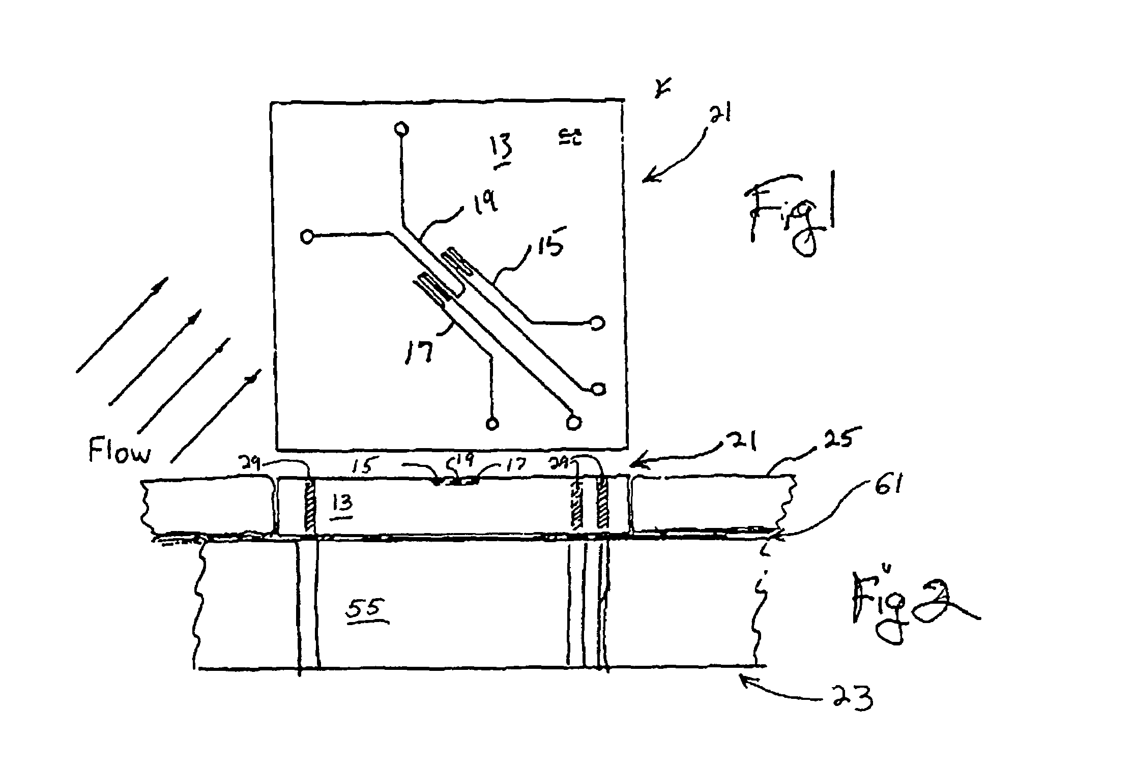
[0029]Referencing FIG. 1, a fluid flow sensor die 21 includes a body 13. Onto body 13 are deposited sensor elements 15, 17 surrounding a central heating element 19; all composed of a suitable metal, such as platinum. The arrangement and theory of operation for a microstructure fluid flow sensor of this type is known to those in the art and will not be further elaborated on herein. Again, for convenience sake, this structure will be generally referred to as a “flow sensor,” as indicated above.

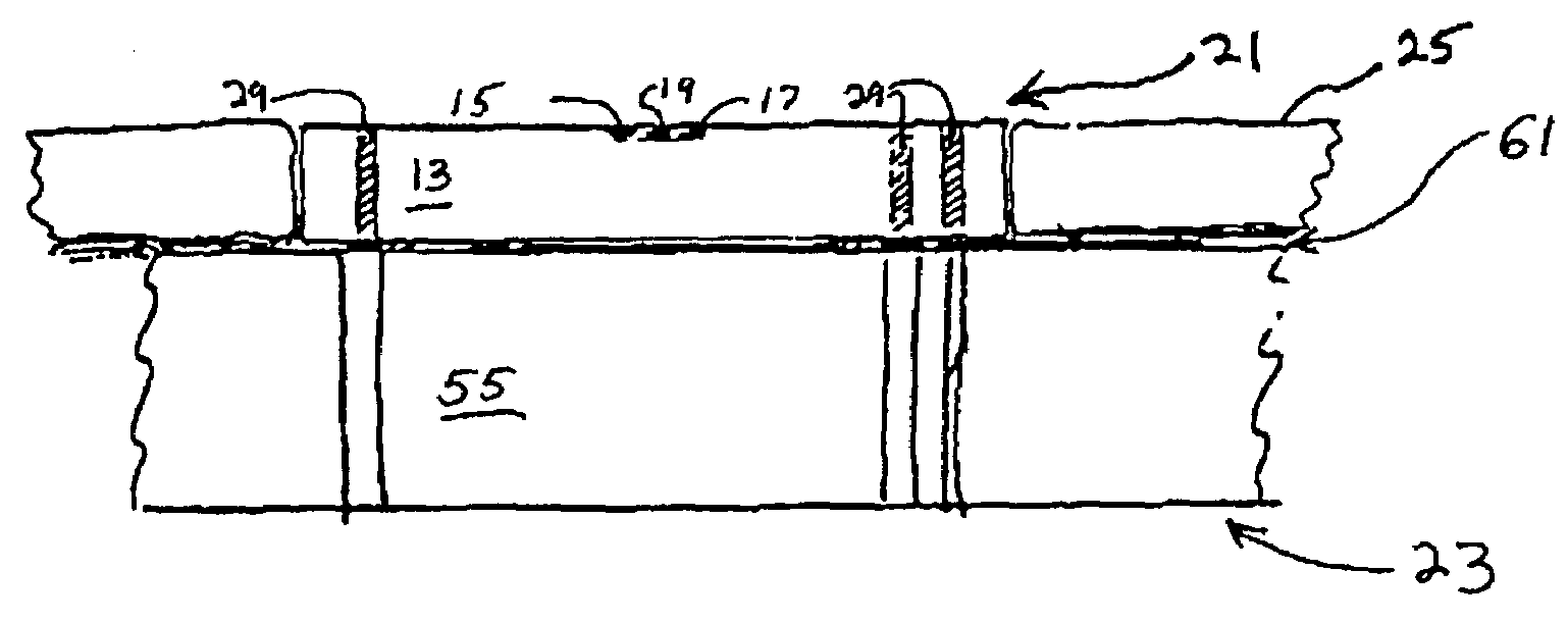
[0030]Referencing FIG. 2, a flow sensor according to the present invention may include a microsensor die 21 bonded to a substrate 23 having a suitably matched coefficient of thermal expansion (CTE). Material for substrate 23 may include alumina, mullite, or known printed circuit board material having suitable CTE. A top surround body, or layer, 25 is placed on the substrate...


PUM


Abstract

A robust sensor that incorporates the necessary physical structure and thermal characteristics is capable of measuring fluid flow and properties under harsh environmental conditions. The sensor die is made of a material with thermal conductivity tailored to provide the thermal transmission characteristics necessary to avoid saturation of the sensor, thus enabling the measurement of high mass flux airflow and liquid properties under high pressure and often harsh environments not previously available for silicon based sensors. The robust sensor further has internal vias for back-side electrical connection, thus avoiding electrical and mechanical interference with the measurements. All of these features come together to provide a microsensor which is capable of reliable, i.e. stable, wide dynamic range and rapid-response operation under harsh environments.

Description

[0001]This is a continuation-in-part of U.S. patent application Ser. No. 09 / 207,165, filed Dec. 7, 1998, entitled “Rugged Fluid Flow and Property Microsensor,” now U.S. Pat. No. 6,184,773, and U.S. patent application Ser. No. 09 / 368,621, filed Aug. 5, 1999 now U.S. Pat. No. 6,322,247, which is a Continuation-in-Part of U.S. patent application Ser. No. 09 / 239,125, filed Jan. 28, 1999 now U.S. Pat. No. 6,361,206, both entitled “Microsensor Housing”.BACKGROUND OF THE INVENTION[0002]1. Field of the Invention[0003]The present invention relates generally to thermal sensors of fluids, such as fluid flow sensors implemented in microstructure form. For convenience sake the term “flow sensor” will be used generically hereinafter for such thermal sensors. The reader will appreciate that such sensors may be utilized to measure primary properties such as temperature, thermal conductivity and specific heat; and that the heat transfers may be generated through forced or natural convection. The inv...

Claims


Application Information

Patent Timeline
IPC IPC(8): H01C7/02G01F1/692G01F1/684G01F5/00G01N1/22G01N25/18G01N25/48G01N33/00
CPCG01F1/6842G01F1/6845G01F5/00G01N25/18G01N25/488G01N33/0014G01N1/2247G01N2001/2285G01F1/684
Inventor PADMANABHAN, ARAVINDBONNE, ULRICHHAJI-SHEIKH, MICHAEL JAMES
Owner HONEYWELL INT INC
Why Eureka
Try Eureka