Method for computer-aided control or regulation of a technical system

a technology of computer-aided control and technical systems, applied in adaptive control, instruments, biological models, etc., can solve the problems of insufficient supply, inability to apply known methods generally to any technical system, and inability to predict dynamic behavior. the effect of minimizing the quadratic error between the predicted and actual sta

Active Publication Date: 2012-04-17
SIEMENS AG
View PDF9 Cites 7 Cited by
  • Summary
  • Abstract
  • Description
  • Claims
  • Application Information

AI Technical Summary

Benefits of technology

[0006]The object of the invention is to create a method for computer-aided prediction of the dynamic behavior of a technical system, which can be applied generally to any technical systems and furnishes good results.
[0010]The inventive recurrent neural network represents a development of the network described in the German patent application DE 10 2007 001 025.9. The development consists of the hidden states of the hidden layer of the recurrent neural network at a respective time point comprising a first hidden state and a second hidden state, with the state of the technical system at the respective time point from the input layer being associated with the first hidden state and the action at the respective time point from the input layer being associated with the second hidden state. The first hidden state at the respective time point is also coupled to the second hidden state at the respective time point by way of a matrix, which is learned during modeling of the dynamic behavior of the technical system. The term matrix here is to be interpreted widely and can optionally also comprise a scalar (i.e. a 1×1 matrix). This allows the dynamic of the technical system to be learned more effectively by taking into account a corresponding matrix between hidden states at the same time point than is the case in the method in the German patent application DE 10 2007 001 025.9. In DE 10 2007 001 025.9 hidden states at the same time point are coupled to one another by way of an identity matrix.
[0014]In one preferred embodiment of the inventive method the first hidden states of the hidden recurrent layer of the recurrent neural network respectively comprise a first number of variables and the second hidden states of the hidden recurrent layer comprise a second number of variables, the first number being different from the second number. In particular the first number is smaller than the second number or vice versa. It is possible in this manner to produce a bottleneck structure, with which the learning of the recurrent neural network is concentrated on the essential, autonomous structure of the dynamic. This allows better modeling of the technical system to be achieved, which in turn results in better learning of the action selection rule by the further neural network.
[0015]In the same way as the hidden states, states of the technical system and the actions also preferably comprise a number of variables. Similarly the hidden states of the further neural network also preferably consist of a number of hidden variables. In particular the number of hidden variables of a hidden state of the recurrent and / or further neural network is smaller here than the number of ambient variables of a state of the technical system. The number of hidden states here is preferably selected so that the method is both data-efficient and also still provides good results.
[0017]In one particularly preferred embodiment, in which the actions are represented at least partially by manipulated variables, the change in the action carried out at the respective time point compared with the temporally preceding action in the output layer of the further neural network is coupled to the action at the respective time point in the input layer of the recurrent neural network by way of a coupling matrix. This matrix can optionally also be a scalar (1×1 matrix). This coupling matrix can be used here to scale or restrict the possible values of the actions, allowing efficient tailoring of the learning of the action selection rule as a function of the technical system so that only possible or expedient actions in the technical system are allowed by way of the coupling matrix. The action at the respective time point in the input layer of the recurrent neural network is preferably coupled here to the temporally preceding action by way of a unit matrix.
[0036]As a result, the equations produce the corresponding matrices A, Â, B, C, D and the corresponding bias θ, which are selected such that the quadratic error between the predicted and actual states is minimized.

Problems solved by technology

The dynamic behavior is however often not simple to predict in the case of complex technical systems, so corresponding computer-aided prediction methods are required, to estimate the future behavior of the technical system and to select appropriate actions for regulating or controlling the technical system correspondingly.
The known methods cannot however be applied generally to any technical systems and often do not furnish sufficiently good results.

Method used


Image

  • Method for computer-aided control or regulation of a technical system
  • Method for computer-aided control or regulation of a technical system
  • Method for computer-aided control or regulation of a technical system

Examples


Embodiment Construction

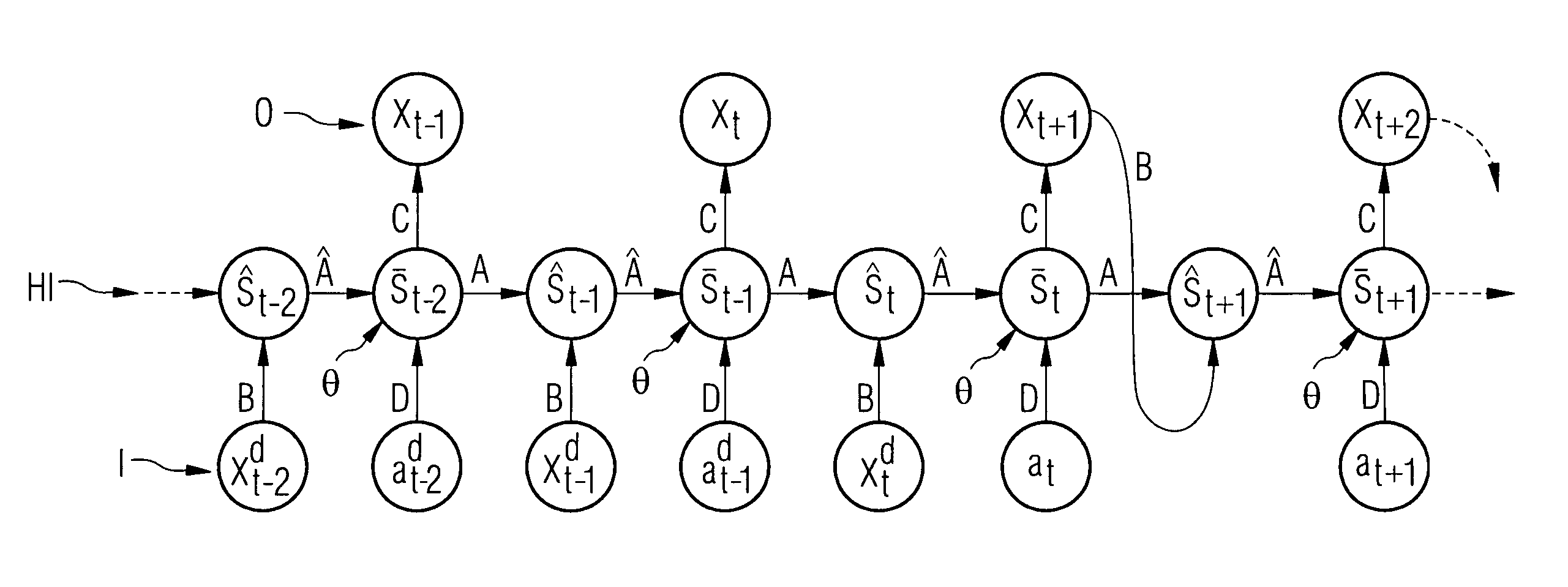
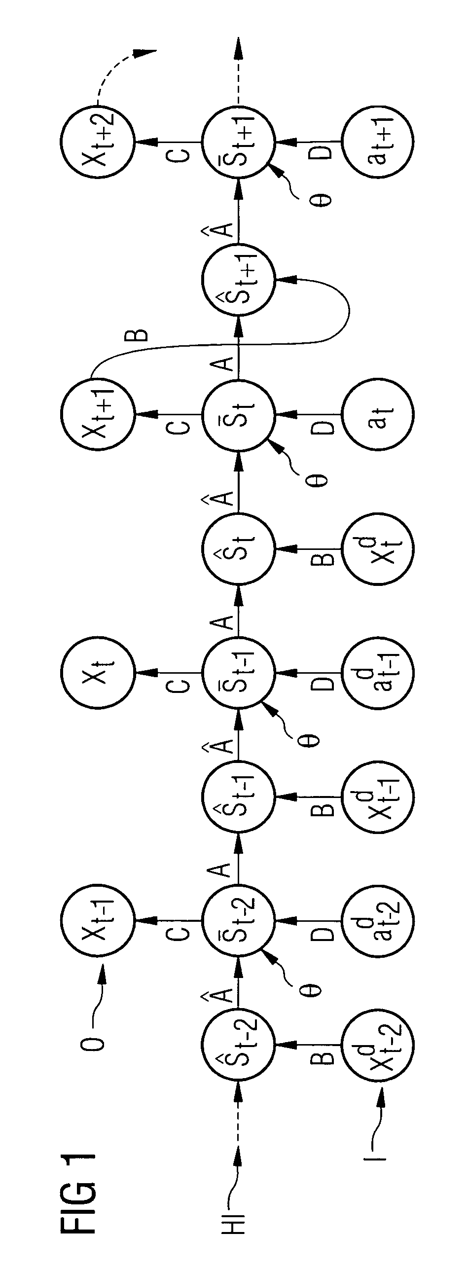
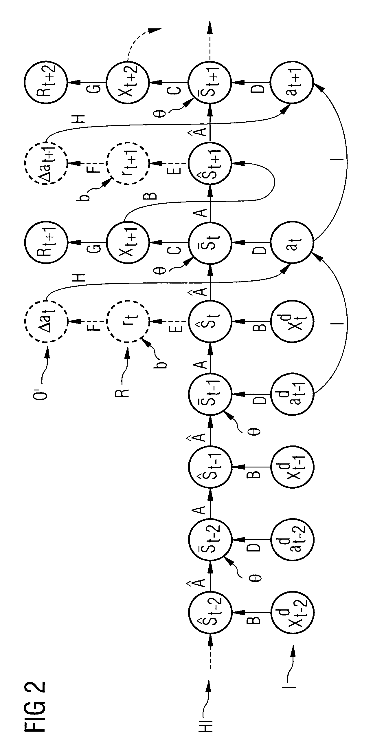
[0052]The inventive method is described in detail below. The method can be applied here to any type of technical system, whose dynamic behavior can be described by a state space X and an action space A with a (stochastic) transition function P(xt, at, xt+1). Here xt, xt+1 ∈ X are states of the technical system at the time points t and t+1, with each state being characterized by a number of state and / or ambient variables. These ambient variables here are measurable state variables of the technical system, for example gas pressure, gas temperature, combustion chamber acceleration and the like in a gas turbine. The actions at ∈ A here are changes in manipulated variables of the technical system at the time point t, which in turn influence subsequent states of the technical system. As with the state xt the action at can also comprise a number of action variables and an action can thus be characterized by the change in a number of manipulated variables. One example of a manipulated varia...


PUM


Abstract

A method for computer-aided control of any technical system is provided. The method includes two steps, the learning of the dynamic with historical data based on a recurrent neural network and a subsequent learning of an optimal regulation by coupling the recurrent neural network to a further neural network. The recurrent neural network has a hidden layer comprising a first and a second hidden state at a respective time point. The first hidden state is coupled to the second hidden state using a matrix to be learned. This allows a bottleneck structure to be created, in that the dimension of the first hidden state is smaller than the dimension of the second hidden state or vice versa. The autonomous dynamic is taken into account during the learning of the network, thereby improving the approximation capacity of the network. The technical system includes a gas turbine.

Description

CROSS REFERENCE TO RELATED APPLICATIONS[0001]This application claims priority of German application No. 10 2008 020 379.3 filed Apr. 23, 2008, which is incorporated by reference herein in its entirety.FIELD OF THE INVENTION[0002]The invention relates to a method for computer-aided control and / or regulation of a technical system and a corresponding computer program product.BACKGROUND OF THE INVENTION[0003]When controlling complex technical systems it is often desirable to select the actions to be carried out on the technical system in such a manner that an advantageous desired dynamic behavior of the technical system is achieved. The dynamic behavior is however often not simple to predict in the case of complex technical systems, so corresponding computer-aided prediction methods are required, to estimate the future behavior of the technical system and to select appropriate actions for regulating or controlling the technical system correspondingly.[0004]The control of technical syste...

Claims


Application Information

Patent Timeline
Patent Type & Authority Patents(United States)
IPC IPC(8): G06E1/00G06G7/00G06F15/18G06E3/00G06N3/00
CPCG05B13/027
Inventor SCHAFER, ANTON MAXIMILIANSTERZING, VOLKMARUDLUFT, STEFFEN
Owner SIEMENS AG
Why Eureka
Try Eureka