Device for Collecting Blood and Separating Blood Constituents, Method for Separating Blood Constituents and Use of Said Device

a technology for separating blood constituents and blood vessels, applied in the field of microfluidic systems and devices, can solve the problems of inability to achieve uniform liquid fronts, inability to ensure optimal filling of sample liquids in channels, and inability to achieve optimal filling of sample liquids. , to achieve the effect of improving the possibility of diagnosis or investigation, and facilitating and rapid determination of plasma constituents

Active Publication Date: 2007-11-22
BOEHRINGER INGELHEIM MICROPARTS
View PDF16 Cites 72 Cited by
  • Summary
  • Abstract
  • Description
  • Claims
  • Application Information

AI Technical Summary

Benefits of technology

[0006] The object of the present invention is to provide a device for collecting blood and separating blood constituents, such as blood plasma, as a sample liquid, a method of separating blood constituents, and uses of the device for easy and rapid determination of plasma constituents and / or of an intracellular parameter, enabling optimum separation of the blood constituents and filling of a channel with sample liquid and, preferably, improving the possibilities of diagnosis or investigation.

Problems solved by technology

However, the design for the channel still does not ensure optimum filling with the sample liquid.
The disadvantage arises that the channels fill up with the sample liquid in the form of blood plasma at different rates or not at all.
Accordingly, it is not possible to achieve a uniform liquid front.
This is disadvantageous in terms of the diagnosis as there are no defined quantities available simultaneously or, for example, dry chemicals or the like cannot simultaneously be dissolved by the sample liquid to the desired or necessary extent.

Method used


Image

  • Device for Collecting Blood and Separating Blood Constituents, Method for Separating Blood Constituents and Use of Said Device
  • Device for Collecting Blood and Separating Blood Constituents, Method for Separating Blood Constituents and Use of Said Device
  • Device for Collecting Blood and Separating Blood Constituents, Method for Separating Blood Constituents and Use of Said Device

Examples


first embodiment

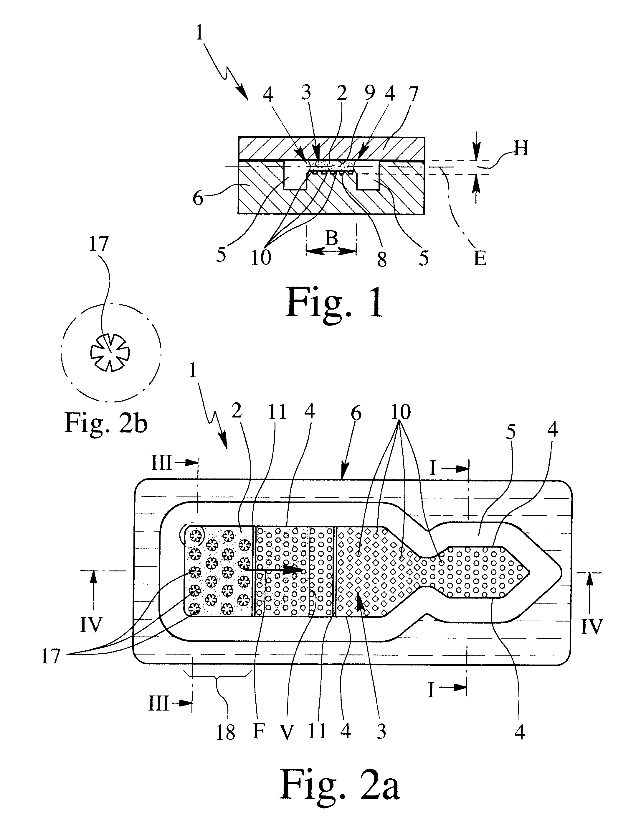
[0036]FIG. 1 shows a schematic section through a proposed device 1 for collecting and / or diagnosing a sample liquid 2, particularly blood plasma or the like.

[0037] The device 1 has a channel 3, which collects the sample liquid 2 by capillary forces. The channel 3 is open in construction, at least on a narrow side or longitudinal side 4, in this embodiment on both narrow or longitudinal sides 4, as shown in FIG. 1.

[0038] Laterally adjoining the open sides 4 is a recess 5 which is preferably groove- or trench-shaped in the embodiment. A lateral liquid stop for the sample liquid 2—i.e. an obstacle to flow which cannot be overcome by capillary forces—is formed in the channel 3 and the sample liquid 2 can be guided along the open sides 4 in the channel 3 without any sidewalls.

[0039] In the embodiment shown, the device 1 has a carrier 6 and an associated cover 7 between which are formed the channel 3 and the recess 5. If necessary, only portions of the carrier 6 are removed in order to ...

fourth embodiment

[0070] The structures 17 form a filling device for (totally) filling the channel 3 between the cover 7 and bottom 8 with sample liquid 2. However, the filling device may also be constructed differently, as explained hereinafter with reference to the

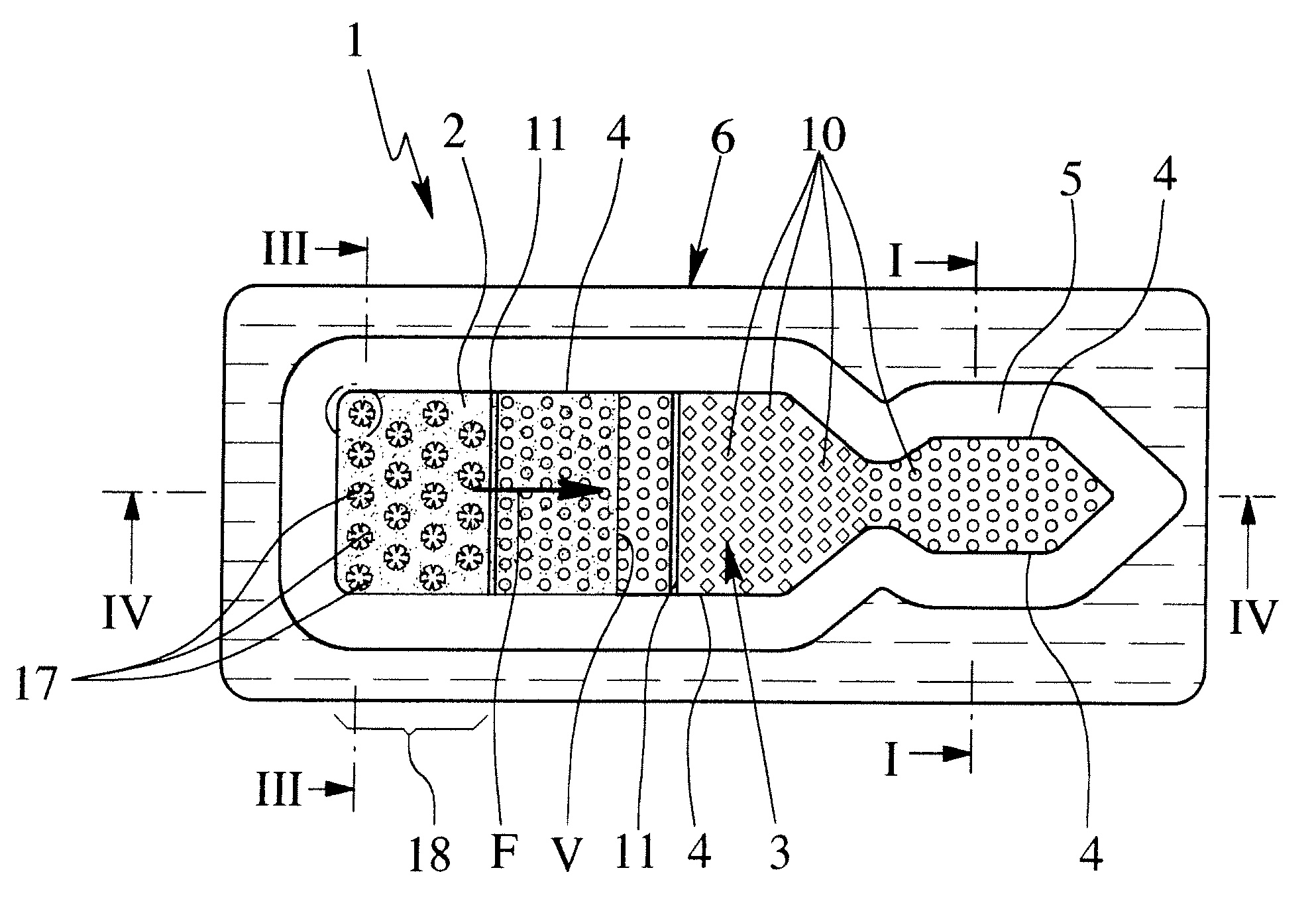
[0071] From the inlet region 18, the sample liquid 2 is sucked further into the channel 3 by capillary forces, as indicated by the main direction of filling F in FIG. 2, after overcoming the first trench 11, in this embodiment.

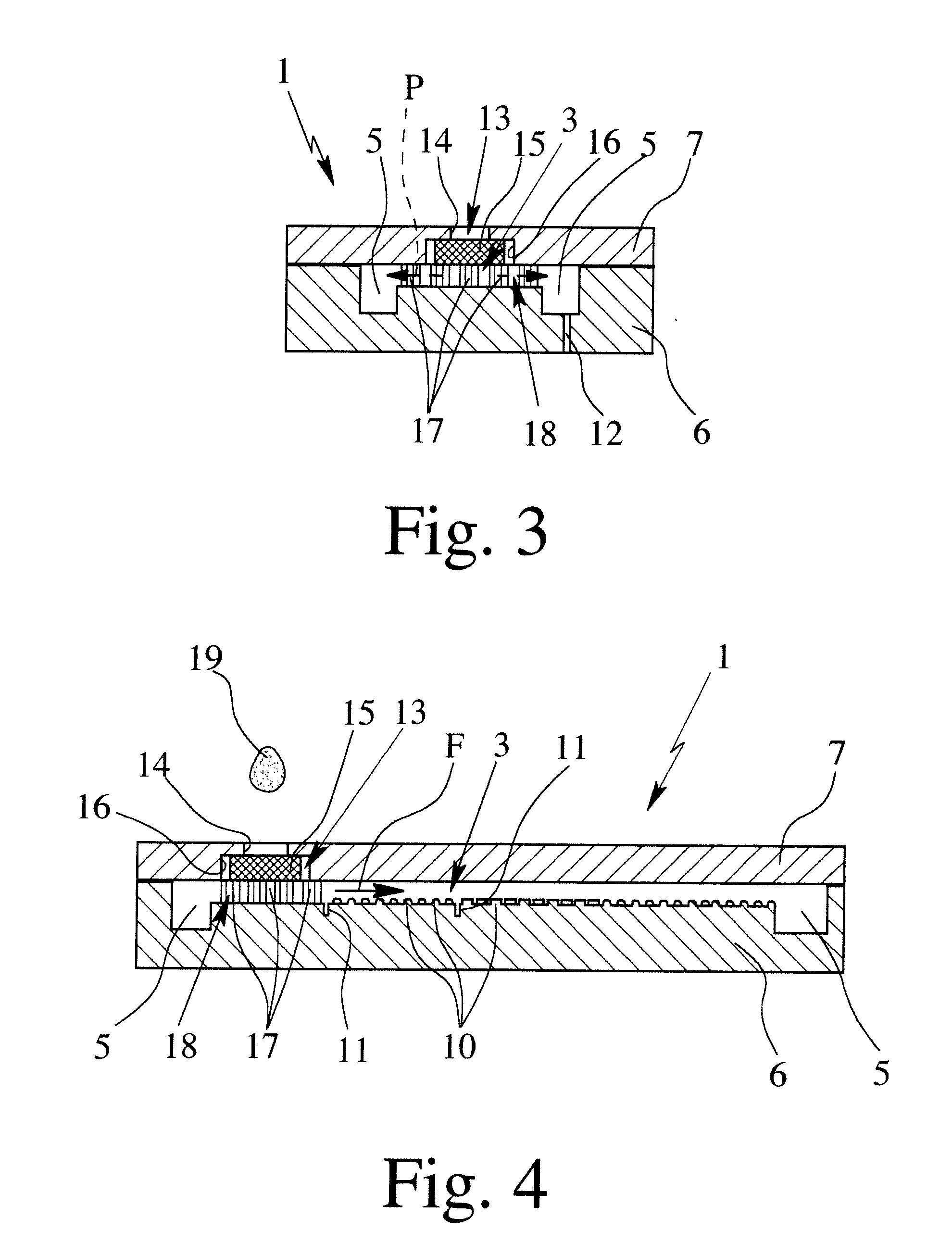
[0072]FIG. 4 shows a schematic longitudinal section through the preferred construction of the proposed device 1 according to the first embodiment, in which a drop of blood 19 supplied thereto is shown for illustration purposes.

[0073] The separator 15 may if necessary contain a chemical, particularly a dry chemical, especially for the purpose of allowing or assisting the separation of blood plasma as a sample liquid 2 from the blood 19, as desirable in the embodiment shown, and / or if necessary to allow the lysing o...

second embodiment

[0074] Preferably, only a single channel 3 adjoins the separator 15, for the purpose of collecting or removing the sample liquid 2. The channel 3 is preferably constructed or intended as an individual capillary. If required, however, the channel 3 may lead in different directions or to different areas or may branch, as explained hereinafter with reference to the second embodiment according to FIG. 5.

[0075]FIG. 5 shows a plan view of the carrier 6 of the device 1 without a cover 7, according to the second embodiment. The channel 3 starting from the feed device 13 or inlet region 18 extends to opposite sides or in opposite directions, for example for the purpose of simultaneously carrying out different investigations, tests or the like. In the embodiment shown, a substantially elongated arrangement is obtained. All kinds of other arrangements are possible, however.

[0076] In the second embodiment, preferably the recess 5 is again provided for at least partly guiding the sample liquid ...


PUM

PropertyMeasurementUnit
heightaaaaaaaaaa
widthaaaaaaaaaa
widthaaaaaaaaaa

Abstract

The invention relates to a device and a method for collecting blood and separating blood plasma as a liquid sample, by means of a canal that absorbs the liquid sample by capillary forces. The aim of the invention is to obtain a uniform filling of the canal with the liquid sample and an effective separation. To achieve this, deaeration takes place in a transverse direction to the main filling direction or to the longitudinal direction of the canal, immediately downstream of a separation device in an inlet region of the canal.

Description

BACKGROUND OF THE INVENTION [0001] 1. Field of the Invention [0002] The present invention relates to microfluidic systems and devices and, more particularly, to a device for collecting blood and separating blood constituents, such as blood plasma, as a sample liquid, in which capillary forces are used and are critical in particular for the function. The present invention also relates to a method of separating blood constituents and to uses of the device for determining an intracellular parameter or for detecting one or more blood constituents. [0003] 2. Description of Related Art [0004] A device for separating liquid components is known from EP 1 013 341 A2, which constitutes the starting point for the present invention, wherein for example blood plasma as a sample liquid is separated from the blood in a filter or a membrane and is collected by capillary forces in a collecting chamber or channel for diagnostic purposes. The channel has a substantially rectangular cross-section. It i...

Claims


Application Information

Patent Timeline
Patent Type & Authority Applications(United States)
IPC IPC(8): G01N33/50B01D17/00B01D29/00B01D35/00B01L3/00G01N33/49
CPCB01L3/502723Y10T436/25375B01L3/502753B01L2200/0621B01L2200/0684B01L2300/0654B01L2300/0681B01L2300/0825B01L2300/0864B01L2300/089B01L2300/161B01L2400/0406B01L2400/084B01L2400/086B01L2400/088B01L3/502746G01N33/491
Inventor BLANKENSTEIN, GERTPETERS, RALF-PETER
Owner BOEHRINGER INGELHEIM MICROPARTS
Why Eureka
Try Eureka