Wavefront sensor and method for determining differences in piston and tilt existing between several light beams

a technology of wavefront sensor and light beam, which is applied in the direction of optical radiation measurement, instruments, measurement devices, etc., can solve the problem of difficult to determine the difference in piston and tilt from any one of the interferograms, and achieve the effect of simple implementation

Active Publication Date: 2019-01-08
OFFICE NAT DETUD & DE RECH AEROSPATIALES
View PDF5 Cites 0 Cited by
  • Summary
  • Abstract
  • Description
  • Claims
  • Application Information

AI Technical Summary

Benefits of technology

[0032]Thanks to the invention, the differences in piston and tilt that exist between the light beams can be determined without using any additional reference wave. The method is thus simple to implement for this reason, without the need for optical components that are dedicated to the generation and the introduction of such a reference wave.

Problems solved by technology

For this reason, the determination of differences in piston and tilt from any one of the interferograms is a difficult task.

Method used


Image

  • Wavefront sensor and method for determining differences in piston and tilt existing between several light beams
  • Wavefront sensor and method for determining differences in piston and tilt existing between several light beams
  • Wavefront sensor and method for determining differences in piston and tilt existing between several light beams

Examples


Embodiment Construction

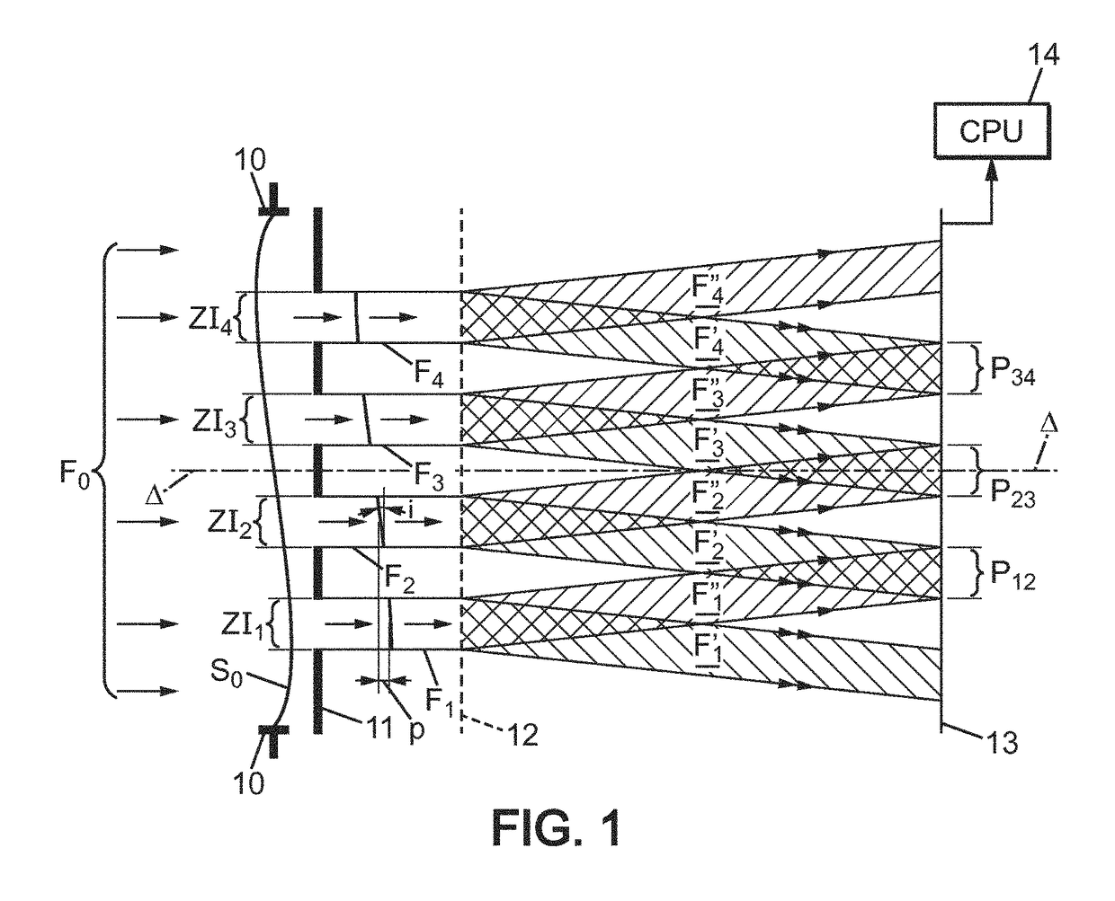
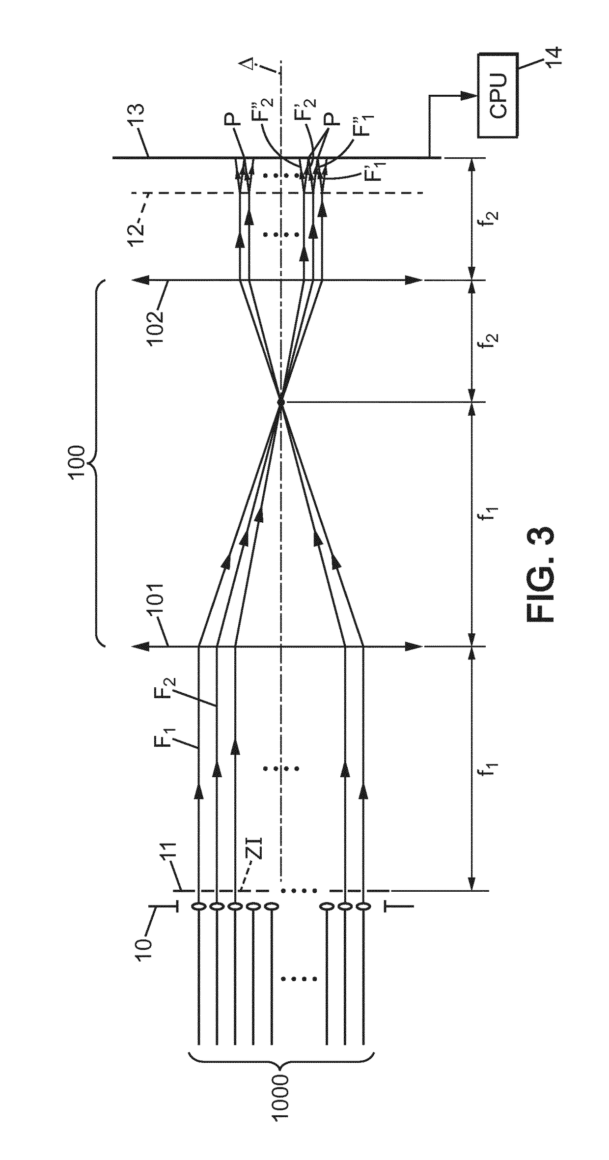
[0040]In the interests of clarity, the dimensions of the different elements represented in the figures do not correspond either to actual dimensions or to actual dimensional relationships. Moreover, identical references that are given in different figures denote identical elements, or those having identical functions.

[0041]The references used in FIG. 1 have the following meanings:

[0042]Δ optical axis of the wavefront sensor

[0043]10 optical input of the wavefront sensor

[0044]11 mask with separate openings

[0045]12 diffraction grating

[0046]13 surface of an image detector

[0047]14 processing module, marked CPU

[0048]F0 initial light beam

[0049]F1, . . . , F4 selected beams within the initial beam F0

[0050]F′1, F″1 sub-beams originating from the beam F1

[0051]F′2 F″2 sub-beams originating from the beam F2

[0052]F′3, F″3 sub-beams originating from the beam F3

[0053]F′4, F″3 sub-beams originating from the beam F2

[0054]S0 initial wavefront

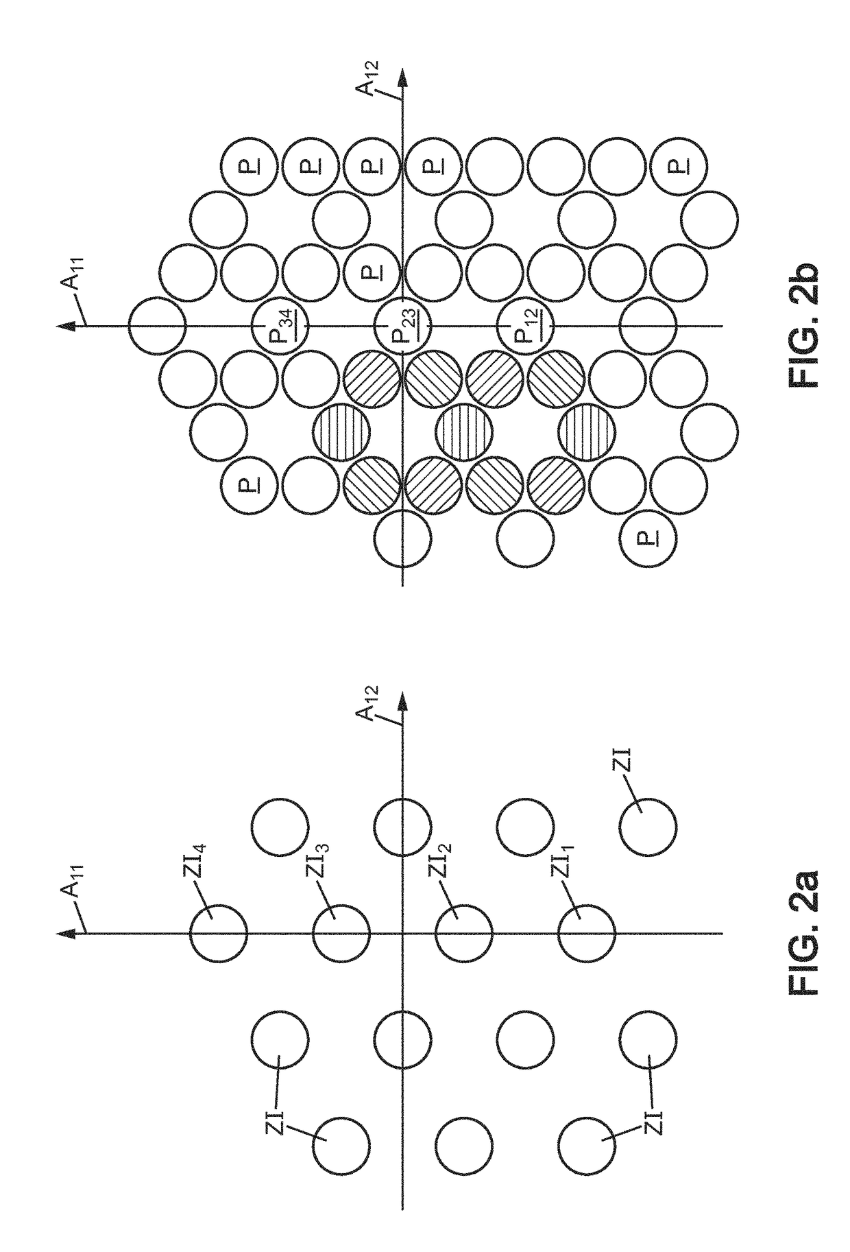
[0055]ZI1, . . . , ZI4 zones of interest

[0056]P12, P23...


PUM


Abstract

A wavefront analyzer is modified to simply determine the differences in amplitude and tilt which can exist between the different regions of an initial wavefront (S0). To achieve this, interference between two waves only is produced from beams (F1, F2) which come from neighboring regions on the initial wavefront. Such an analyzer can be used to coherently combine laser radiation produced by different sources arranged in parallel. Another use is for the determination of the differences in height and inclination which exist between the neighboring mirror segments of a Keck telescope.

Description

[0001]The present invention relates to a wavefront sensor based on interference. It also relates to a method for determining differences in piston and tilt existing between several light beams capable of producing interferences.[0002]In the present description, the expressions “wave surface” and “wavefront” are understood to be synonyms. Similarly, the terms “interference pattern” and “interferogram” are also used as synonyms. The term “tilt” is used to denote the inclination of a wavefront, and “piston difference” denotes the mean difference in advance that exists between two wavefronts, each wavefront advance being measured in its direction of propagation.[0003]The thus-defined piston difference applies regardless of the spectral composition of the light radiation. For this reason, it can also be called absolute piston difference. However, for monochromatic light radiation, due to the spatial periodicity of the electromagnetic field, only a residual part of the piston difference i...

Claims


Application Information

Patent Timeline
Patent Type & Authority Patents(United States)
IPC IPC(8): G01B11/02G01J9/02G01J9/00
CPCG01J9/02G01J9/0215G01J2009/002
Inventor BELLANGER, CINDYDEPREZ, MAXIMELOMBARD, LAURENTPRIMOT, JEROME
Owner OFFICE NAT DETUD & DE RECH AEROSPATIALES
Why Eureka
Try Eureka