Spatial accuracy correction method and apparatus

a correction method and technology of spatial accuracy, applied in the field of spatial accuracy correction methods and apparatuses, can solve the problems of high-accuracy corrections that cannot be performed, errors are incorporated into measurements, etc., and achieve the effect of high degree of correction accuracy

Active Publication Date: 2022-06-21
MITUTOYO CORP
View PDF9 Cites 0 Cited by
  • Summary
  • Abstract
  • Description
  • Claims
  • Application Information

AI Technical Summary

Benefits of technology

[0016]The present invention provides a spatial accuracy correction method and apparatus having a high degree of correction accuracy.
[0020]In the present invention, the plurality of measurement points are divided into a plurality of measurement lines that include a predetermined number Ka of measurement points for example, and the repeated measurement is conducted for each measurement line. In such a case, compared to a case where all the plurality of measurement points are measured again, appropriate measured value and measured length value with respect to the each measurement point can be acquired rapidly.
[0023]In the spatial accuracy correction method of the present invention, at least one or more measurement points that undergo the repeated measurement is preferred to include the measurement point initially measured on the measurement line. In the present invention, when the repeated measurement is conducted, the initial measurement point being measured is included as a measurement point for the repeated measurement. When the position of the tracking-type laser interferometer becomes offset due to temperature drift or an external impact during measurement of the plurality of measurement points, the measured length value from the repeated measurement at the measurement point initially being measured is always different from the measured length value prior to the repeated measurement. Therefore, by having the measurement point initially being measured undergo the repeated measurement, a determination can be made easily and rapidly whether the measurement should be conducted again for the plurality of measurement points.
[0024]According to the spatial accuracy correction method of the present invention, in the repeated measurement, preferably, the plurality of measurement points are measured in a reverse order of the measurement of the plurality of measurement points being measured most recently. In the present invention, when the repeated measurement is conducted, measurement is conducted in the reverse order of the measurement of the plurality of measurement points being recently measured. Accordingly, when the measured length value is gradually increased or decreased by temperature drift and the like, for example, it is possible to cancel out the effect by temperature drift by finding the least square value between the measured length value at each measurement point from the repeated measured and the measured length value of each of recent measurement points, for example. In addition, when temperature drift is occurred while the repeated measurement is conducted, compared to a case where the measured length value is acquired by displacing each of the measurement points in the same direction with the recent measurement point, a case where the measured length value is acquired by displacing the measurement points in the reverse order causes a greater repeat error. For example, measurement is conducted in order from a measurement point X1 to a measurement point XKa, and the measurement is conducted in order from the measurement point XKa to the measurement point X1 in the repeated measurement, the difference (repeat error) between the measured length value during the repeated measurement and the recent measured length value at X1 is increased when temperature drift occurs. Therefore, the determination whether to conduct a measurement again for each measurement point, that is, the determination whether the error is included in the measured length value due to displacement of the rotation center M can be appropriately made, and a highly accurate spatial accuracy correction can be performed.

Problems solved by technology

In such a case, there is a possibility that the error is incorporated into the measurement points onward the measurement point that has undergone the repeated measurement.
When a correction parameter is calculated based on the measured value before conducting the repeated measurement, a high-accuracy correction cannot be performed.

Method used


Image

  • Spatial accuracy correction method and apparatus
  • Spatial accuracy correction method and apparatus
  • Spatial accuracy correction method and apparatus

Examples


first embodiment

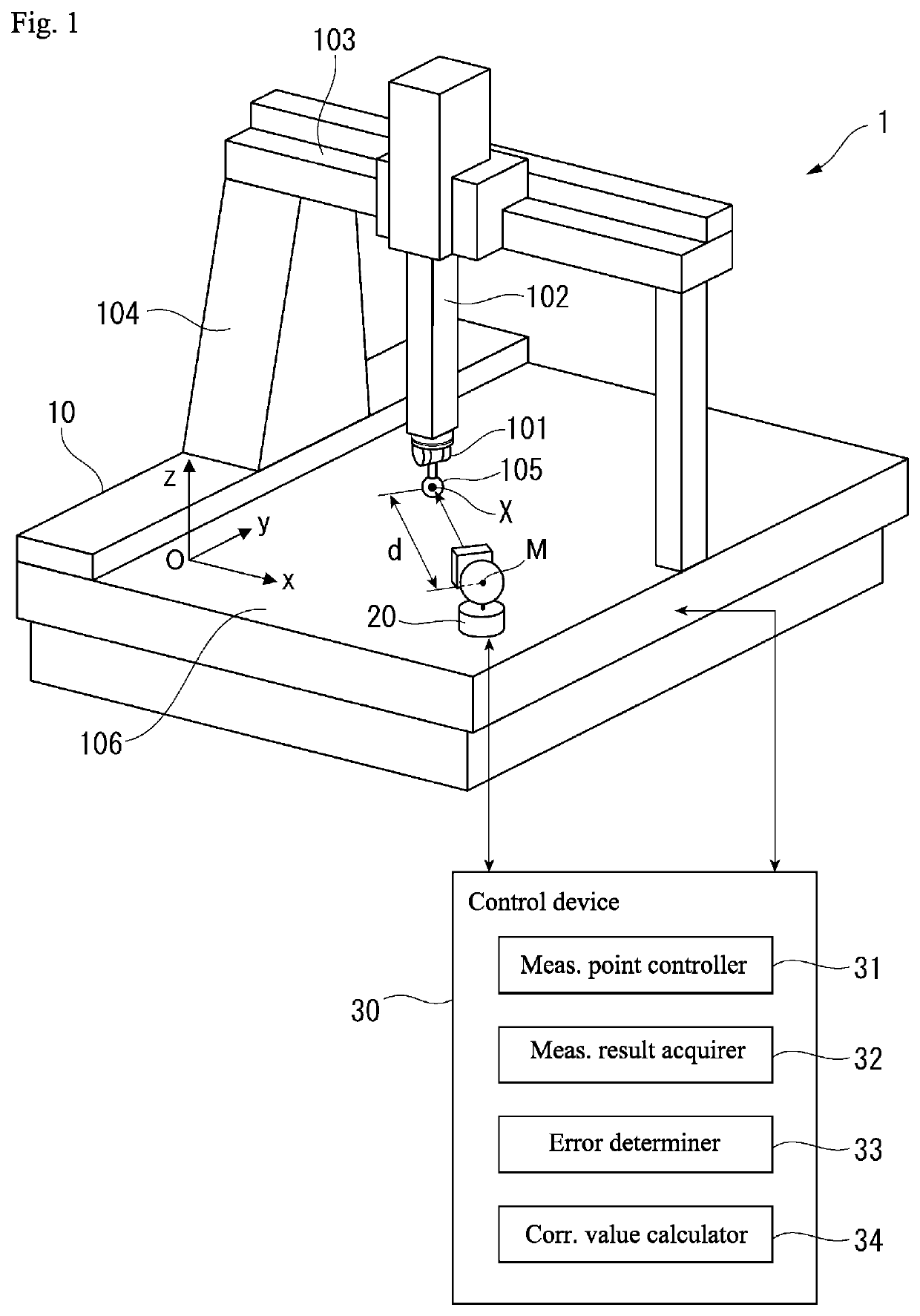
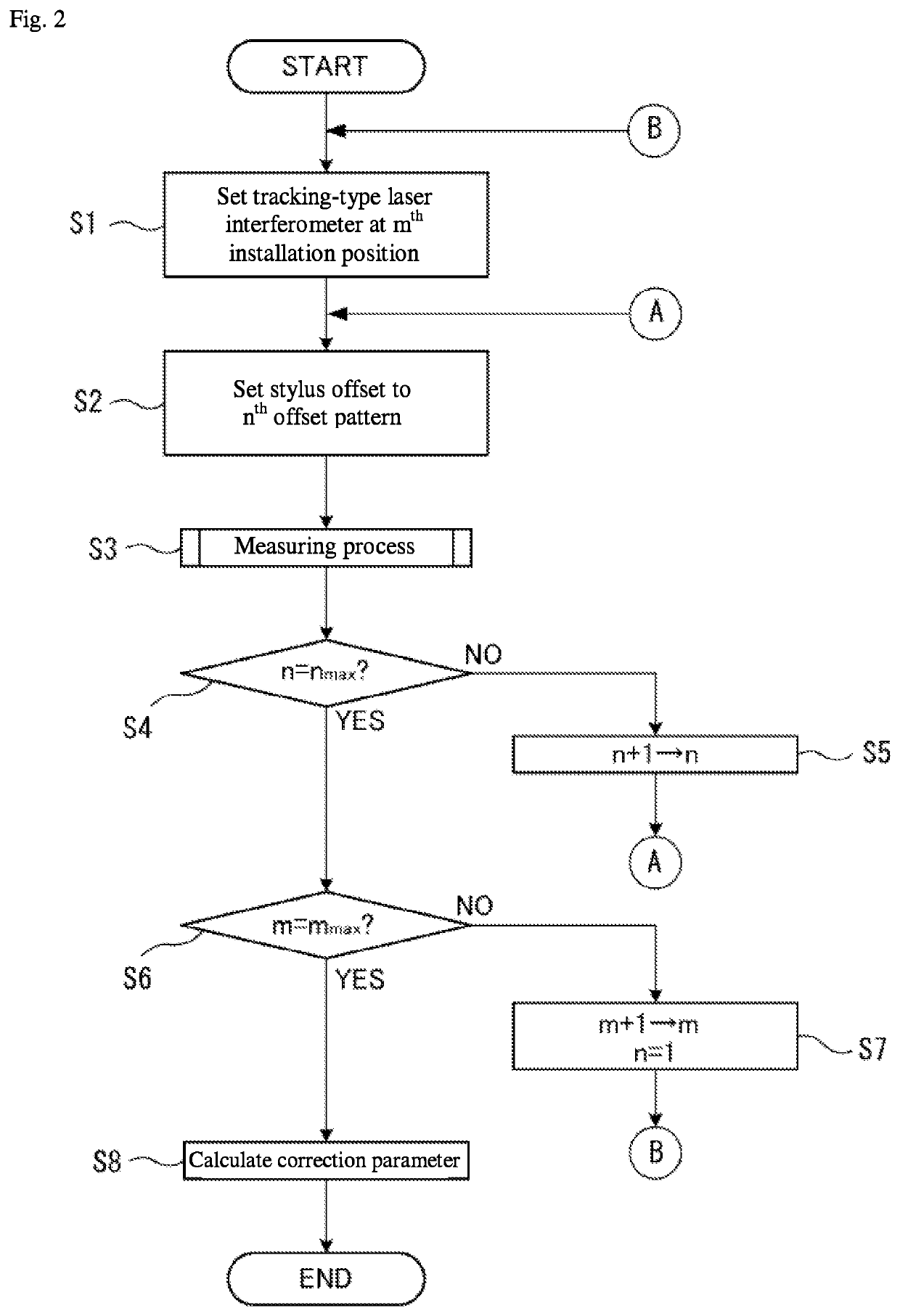
[0036]Hereafter, a spatial accuracy correction apparatus according to an embodiment of the present invention is described. FIG. 1 illustrates a schematic configuration of a spatial accuracy correction apparatus 1 according to the embodiment. The spatial accuracy correction apparatus 1 includes a CMM 10, a tracking-type laser interferometer 20, and a control device 30. In FIG. 1, the CMM 10 and the tracking-type laser interferometer 20 have the same configuration as the conventional example illustrated in FIG. 7. Specifically, the CMM 10 is equivalent to a positioning mechanism or machine in the present disclosure, and includes a measurement probe 101, a Z spindle 102 to which the measurement probe 101 is affixed, an X guide 103 holding the Z spindle 102 so as to be capable of displacement in an X direction, and a column 104 to which the X guide 103 is affixed and which is capable of displacement in a Y direction. In addition, the CMM 10 includes a Y displacement mechanism, an X disp...

second embodiment

[0063]Next, a second embodiment is described. In the following description, portions identical to those which have been previously described are assigned identical reference numerals and a description thereof is omitted or simplified. According to the first embodiment described above, in the parameter calculation step in step S8, values of the measured value XCMM and measured length value d acquired in step S3 are substituted into Expressions (1) and (2) and calculated the correction parameter by using the least square method. At this time, different correction constants were applied to the first correction constant Fd (correction constant of the measured length value d) and the second correction constant FM (correction constant of the coordinates of the rotation center M) when the position of the rotation center M is changed and when the stylus offset is changed. In contrast, in a second embodiment, when the position of the rotation center M is changed in addition to when the stylu...

third embodiment

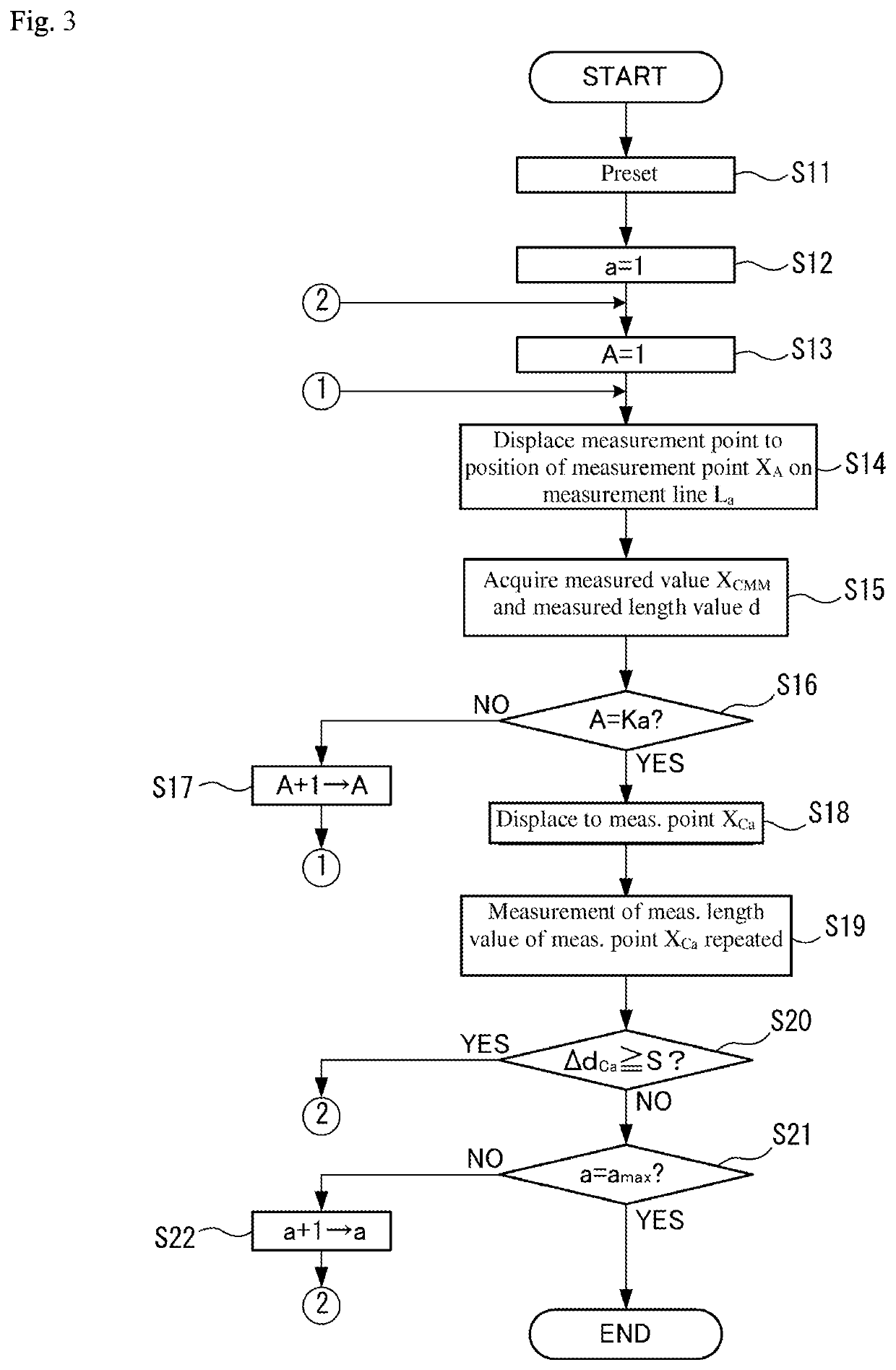
[0069]Next, a third embodiment is described. In the first embodiment described above, the measurement point XCa for the repeated measurement in step S19 is the initial measurement point X1 on the measurement line La. In contrast, the third embodiment differs from the above-described first embodiment in that the plurality of measurement points X belonging to the measurement lines La are measured as the measurement point XCa.

[0070]FIG. 5 illustrates an exemplary measurement order of measurement points according to the third embodiment. Specifically, in the present embodiment, the measurement point XCa for the repeated measurement is all the measurement points X included in the measurement lines La and the measurement is conducted in a reverse direction from the recent measurement direction of the measurement points. In the example shown in FIG. 5, a number Ka of measurement points X belong to the measurement line La, for example. In such a case, in step S15, in order from the measurem...


PUM


Abstract

A spatial accuracy correction apparatus performs a spatial accuracy correction of a positioner displacing a displacer to a predetermined set of spatial coordinates using a measurable length value measured by an interferometer and a measurable value of the set of spatial coordinates of the displacement body that is measured by the positioner. The measured length value and the measured value for each measurement point are acquired by displacing the displacement body to a plurality of measurement points in order, one or more repeated measurements are conducted for at least one of the plurality of measurement points being measured after conducting measurement of the measured length value and the measured value for each of the plurality of measurement points, and the plurality of points are measured again when a repeat error of the measured length value is equal to or greater than a threshold value.

Description

CROSS-REFERENCE TO RELATED APPLICATIONS[0001]The present application claims priority under 35 U.S.C. § 119 of Japanese Application No. 2017-240065, filed on Dec. 14, 2017, the disclosure of which is expressly incorporated by reference herein in its entirety.BACKGROUND OF THE INVENTION1. Field of the Invention[0002]The present invention relates to a spatial accuracy correction method and apparatus that correct an error in positioning in a positioning mechanism that positions a displacement body at a predetermined set of spatial coordinates.2. Description of Related Art[0003]Conventionally, a positioning mechanism is known that positions (displaces) a displacement body at a predetermined coordinate position in space (spatial coordinates). Examples of such positioning mechanisms may include a coordinate measuring machine (CMM) that displaces a measurement probe to measure a shape of an object, a machine tool that displaces a processing tool to process an object, a robot that displaces ...

Claims


Application Information

Patent Timeline
Patent Type & Authority Patents(United States)
IPC IPC(8): G05B19/401G01B9/02055G01B21/04
CPCG05B19/401G01B9/0207G01B9/02071G01B9/02072G01B21/045G01B2290/15G05B2219/37275G05B2219/39033G05B2219/41094G05B2219/50057G01B21/042
Inventor YANAKA, SHINICHIRONARA, MASAYUKI
Owner MITUTOYO CORP
Why Eureka
Try Eureka