

Roller chain transmission device
- Summary
- Abstract
- Description
- Claims
- Application Information
AI Technical Summary
Benefits of technology
Problems solved by technology
Method used
Image

Examples
Embodiment Construction
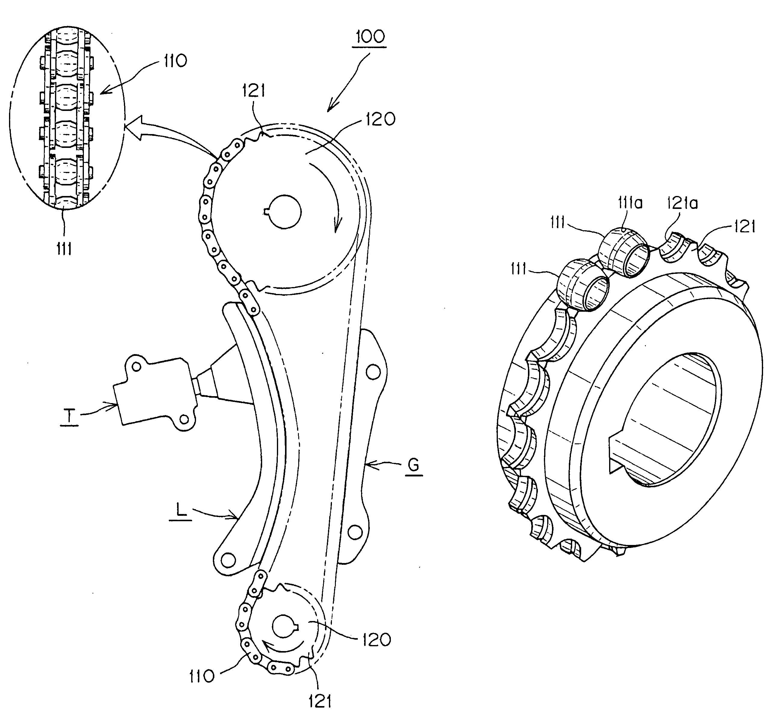
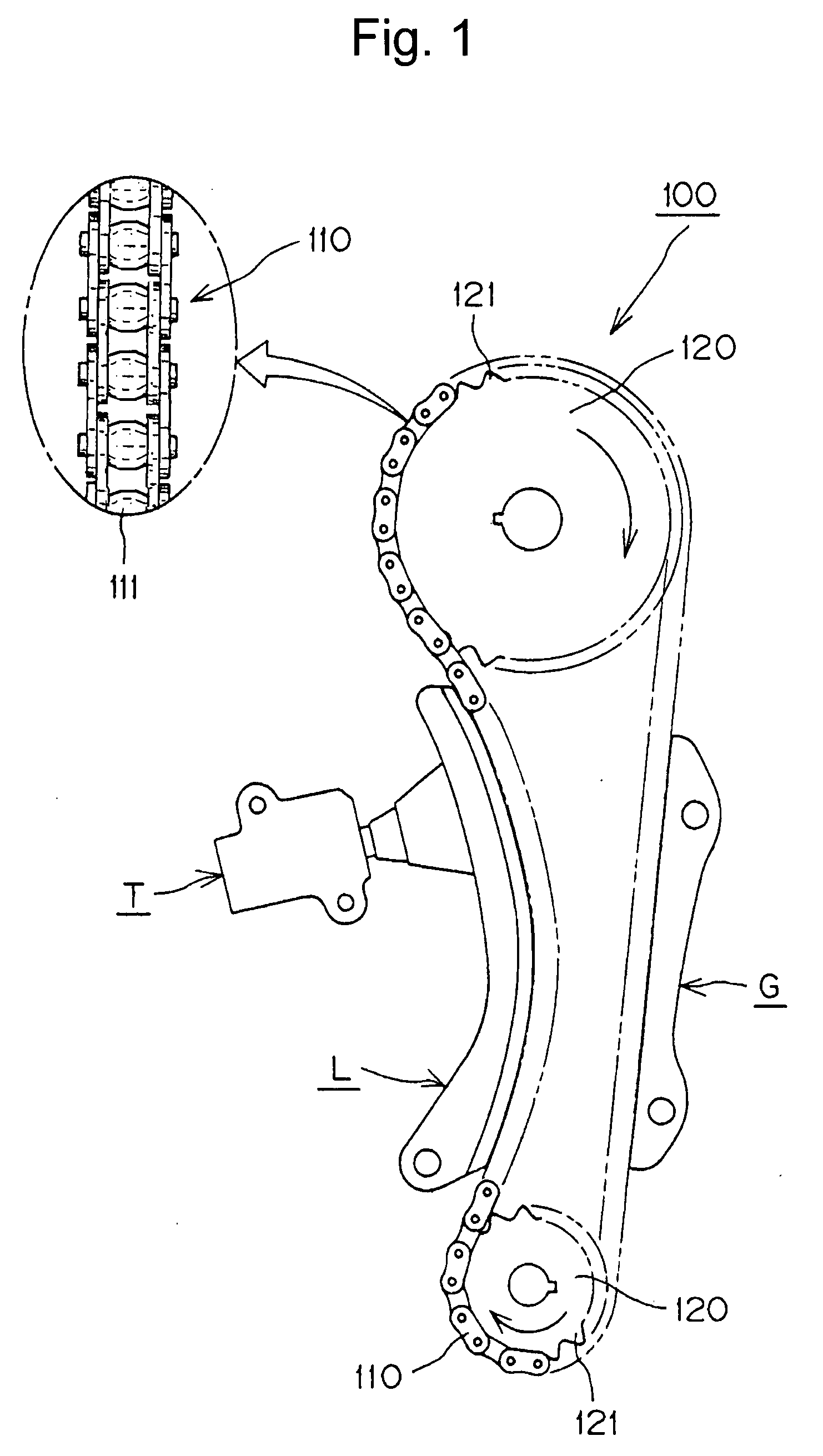
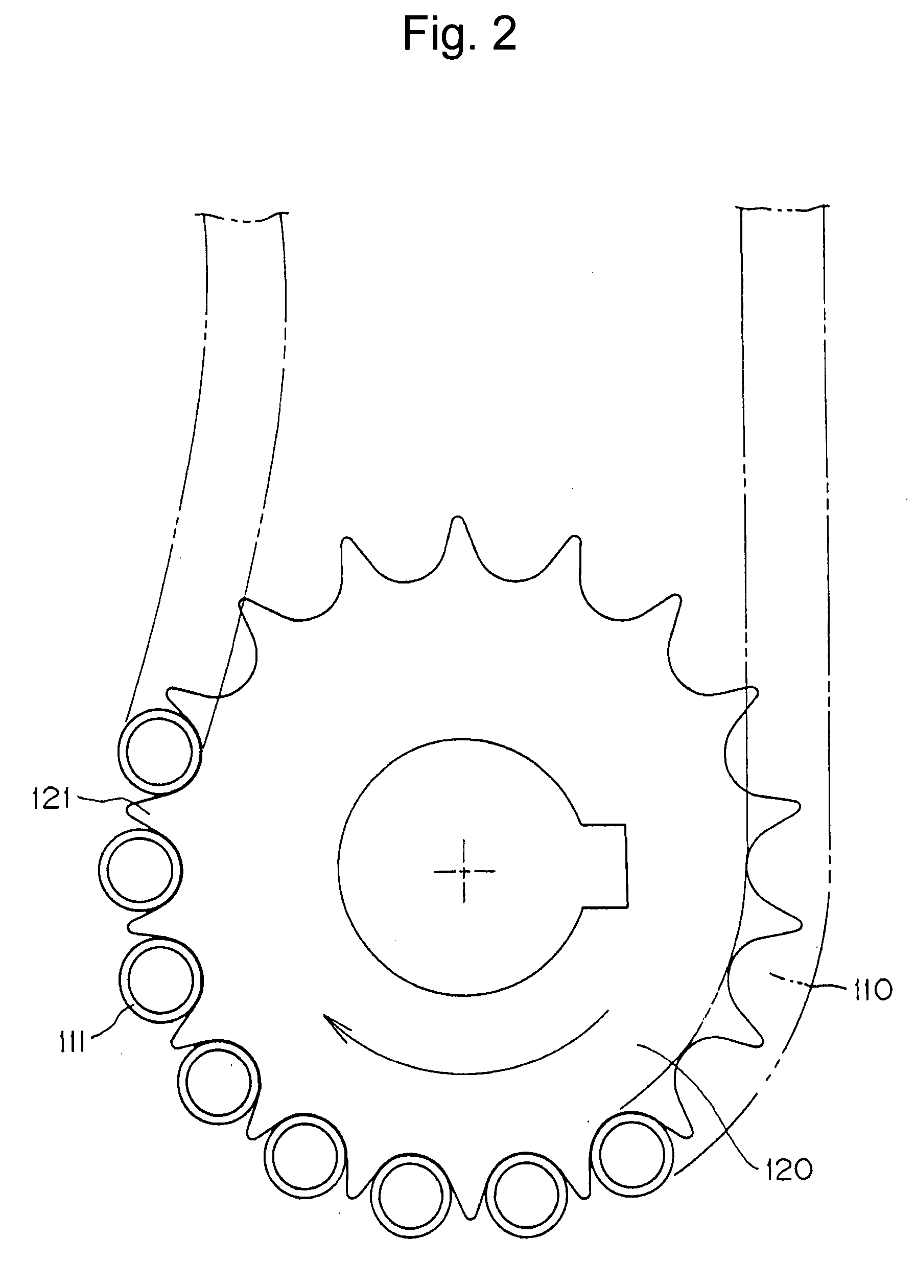
[0032]The advantages of the roller chain transmission according to the invention, namely, the suppression of impact force and vibration, the reduction of engagement starting noise, and increased endurance, can be realized in various embodiments. In each embodiment, the rollers have a barrel-shaped outer circumferential surface, in which the diameter gradually decreases, from a central region toward the ends portions of the rollers, and the sprocket teeth have concave surfaces which engage the outer circumferential surfaces of the rollers on both sides of the central region.
[0033]The inner and outer plates of the chain can have any of various shapes, including, for example, a shape in which the intermediate region between the pin holes has parallel upper and lower edges, an oval shape having an expanded intermediate region, and a gourd-like shape having a pinched intermediate region. The sprocket can be made by any of various processes, including, for example, casting, sintering, and...
PUM
 Abstract
Description
Claims
Application Information