
Adapter, a fixation pin and a method for fixation of a supporting structure to a body part

a technology of fixing pins and supporting structures, applied in the field of adapters, fixing pins and fixing methods, can solve the problems of today's fixing pins, burn injuries of patients, artefact or distortion problems of images or attenuation of signals, etc., and achieve the effect of reducing the total cost of manufacturing

Inactive Publication Date: 2007-11-22
ELEKTA AB
View PDF6 Cites 13 Cited by
  • Summary
  • Abstract
  • Description
  • Claims
  • Application Information

AI Technical Summary

Benefits of technology

[0012] The object of the invention is to provide an adapter, which will reduce the total costs for manufacturing and using fixation pins for fixation of a supporting structure to a body part. At least this object will be achieved by an adapter for a fixation pin of the type which is adapted for fixating a supporting structure to a bony structure of a human or animal body part, and which is provided with a shank portion, the adapter comprising a sharp-pointed tip for penetration into the bony structure of the body and an engagement formation for removable connection to an inner end of said shank portion.
[0018] In this way several advantages may be achieved. The fixation pin can be manufactured of a homogenous and durable material, e.g. a metal, which will enable the fixation pin to be manufactured to a low cost compared to a fixation pin having integrated tip and shank portions of different materials. The adapter can be made of a low cost material, having a strength and stiffness high enough for performing at least one fixation and subsequently the adapter can be disposed off. The shank portion, on the other hand, can be made of a more durable, and hence more expensive material and reused over and over again. The adapter, which will have contact with tissue and therefore possesses the largest risk to transfer infection to the patient, can be delivered thoroughly sterilized, contained in a sterile package, whereas the shank portion can be sterilized by autoclaving and / or chemicals and consist of a material that withstands repeated sterilization. In this way it is, in case there is desirable to have different materials in the adapter and the shank portion, possible to make the shank portion of a homogeneous material which will eliminate the risk of forming of cracks in the fixation pin during sterilization. It is possible to form the adapter of a polymeric or plastic material or other electrical and heat insulating material, which during MR-imaging will reduce artefact or distortion of the images and attenuation, and protect the patient against excessive heat generated by RF-energy during imaging, while the shank portion can be formed of a more strong and durable material. It is possible to form the adapter of a low density material, such as a polymeric or plastic material, which during CT-imaging will decrease artefacts and distortion of the images. The adapter can be manufactured by a low cost method, e.g. by injection moulding of a plastic material, which will ensure a low total cost for each adapter. An adapter, which will give the above advantages, can easily be adapted to fit on existing fixation pins without the need for replacing existing equipment.
[0019] Within the general idea, the invention can be realized in many different ways. Normally, it is preferred to form the adapter of a polymeric or plastic material, such as PEEK, PAI, PEI or other polymers commonly used in medical devices, which is comparatively cheap, can easily be formed to a low cost, is heat insulating and electrically insulating, at least if it doesn't contain any electrically conducting fillers or fibres like carbon fibres. The shank portion, on the other hand, is preferably formed of a strong and durable metallic material, such as aluminium or titanium, which can be sterilized and reused over and over again.

Problems solved by technology

However, there are different problems with the fixation pins used today.
When MR-imaging, pins made of conducting material tend to induce RF-energy (Radio Frequency) at the tip which has caused burn injuries of patients.
This problem is not present when using plastic pins as long as the pins does not contain conducting fillers or fibres like carbon fibres.
Another common problem in MR-imaging is artefact or distortion problems of images or attenuation of the signals, which is caused by magnetic trace material in mainly hard metal tips and titanium.
Hard metal and ceramic are high density materials where this problem is significant.
Plastic reusable pins are usually more sensitive to these methods and the material will degrade in an uncontrolled way that may be hazardous to the patient.
There are not many commercial plastic pins left on the market today.
Autoclaving in high temperatures have shown to induce cracking of the pin bodies due to different characteristics of the materials.
The cost for manufacturing pins having an integrated tip of a different material, are much more expensive than for homogenous pins with tip and shank in the same material.
However, pins of only one material can not be manufactured in a material that have a tip strength that makes the pins fully reusable and the cost for using these pins as disposables will be too expensive.
However, plastics have a lower rigidity in comparison to aluminium and titanium.
Accordingly, the pin diameter must be increased which has to result that the pins will not fit into existing stereotactic frames made for metallic pins.
Moreover, this pin has not the same hygienic advantages as single use pins.
There is also mechanical problems that can arise when combining two materials having different characteristics such that it will not hold for autoclaving as well as other, chemical sterilizing methods.-This together with the choose of tip will probably result in high costs for this solution.

Method used


Image

  • Adapter, a fixation pin and a method for fixation of a supporting structure to a body part
  • Adapter, a fixation pin and a method for fixation of a supporting structure to a body part

Examples


Embodiment Construction

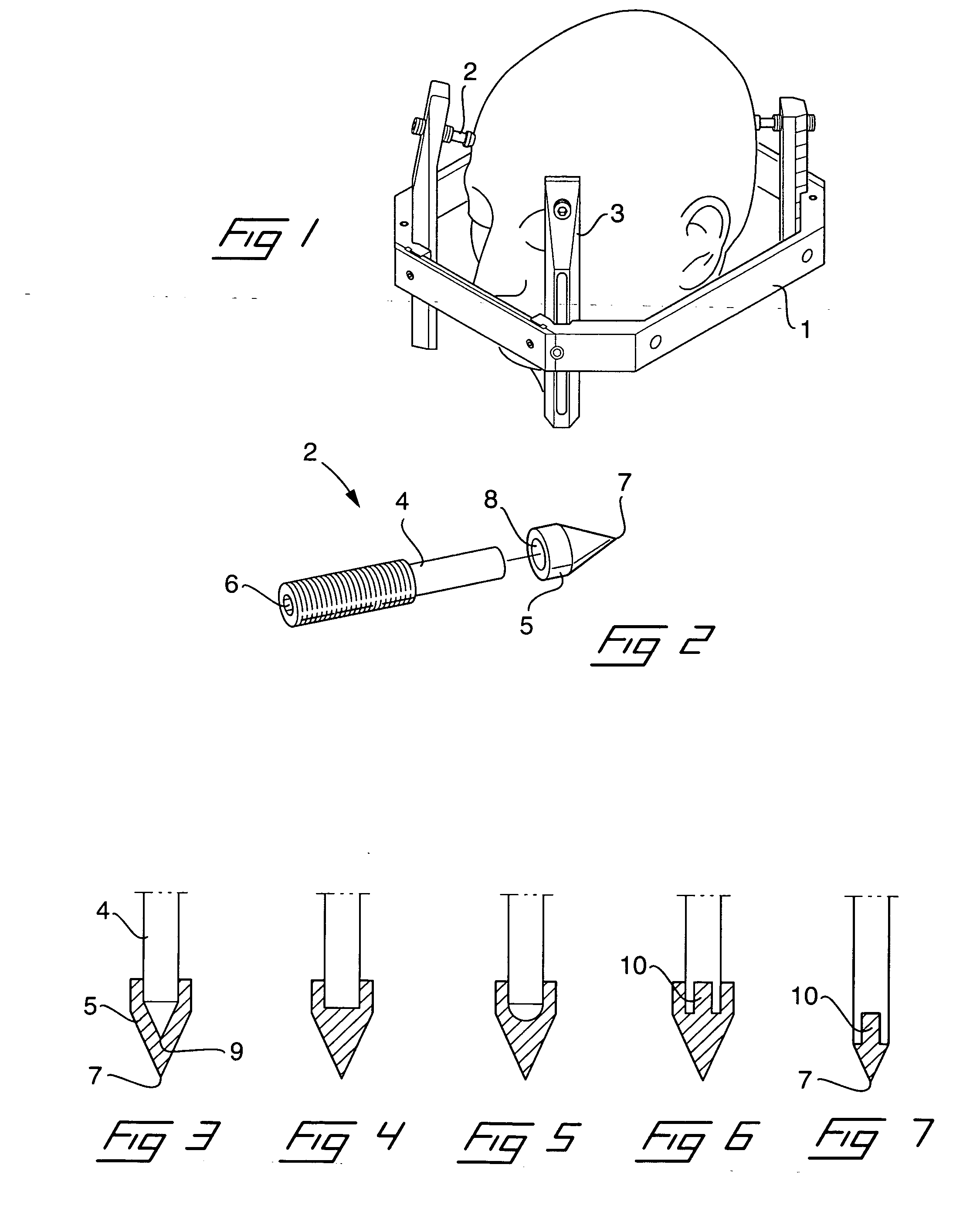
[0028] In FIG. 1 is shown an example of a supporting structure attached to a body part. In this case the supporting structure is a so called stereotactic frame 1, which is attached to a head of a patient by means of four fixation pins 2, of which only three is visible in the drawing. The stereotactic frame 1 is ring shaped and has four upward directed posts 3, which are adjustable in relation to the frame 1. In the upper end of each post 3, a fixation pin 2 is screwed into a threaded hole in the post such that a sharp-pointed tip of each fixation pin penetrates a small distance into the tissue and the skull and rigidly attaches the frame to the head.

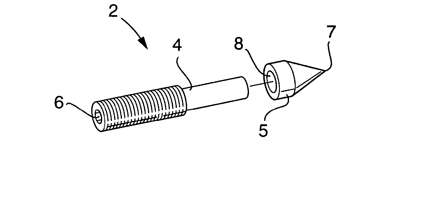
[0029]FIG. 2 shows an exploded perspective view of an exemplary embodiment of a fixation pin 2 according to the invention. The fixation pin comprises a shank portion 4 and an adapter 5, of which the latter is detachable mountable to an inner end of the shank portion. As can be seen, the shank portion 4, in this embodiment, is formed wit...


PUM


Abstract

The invention relates to an adapter (5) for a fixation pin (2) of the type which is adapted for fixating a supporting structure to a bony structure of a human or animal body part, and which is provided with a shank portion (4). The adapter (5) comprises a sharp-pointed tip (7), for penetration into the bony structure of the body part, and an engagement formation (8) for removable connection to an inner end of said shank portion (4). The invention also relates to a fixation pin and a method for fixating a supporting structure to a human or animal body part.

Description

[0001] The invention relates to an adapter for a fixation pin of the type which is adapted for fixating a supporting structure to a bony structure of a human or animal body part, said fixation pin comprising a shank portion and being displaceably mounted in the supporting structure such that an inner end of the shank portion can be advanced towards or retracted from the body part to which the supporting structure is to be fixated. [0002] The invention also relates to a fixation pin as well as a method for fixation of such a supporting structure to a bone of a human or animal body part. BACKGROUND OF THE INVENTION [0003] During treatment or diagnosis of humans or animals, it is in many cases common practice to attach some kind of supporting structure to the bone or bony structure of the body part to be treated or examined. This can be done for purpose of fixation of two body parts in relation to each other, for fixation of a body part in relation to a treating or diagnosing apparatus...

Claims


Application Information

Patent Timeline
Patent Type & Authority Applications(United States)
IPC IPC(8): A61B17/00
CPCA61B17/62A61B17/6433A61B19/203A61B17/866A61B17/8685A61B17/8635A61B90/14
Inventor ARN, THOMASNILSSON, BO
Owner ELEKTA AB
Learn More