Locking compression hip screw

a hip screw and compression technology, applied in the field of compression hip screws, can solve the problems of displacement of major fracture fragments by shearing

Active Publication Date: 2007-11-22
SHAW JAMES ALBERT
View PDF21 Cites 47 Cited by
  • Summary
  • Abstract
  • Description
  • Claims
  • Application Information

AI Technical Summary

Benefits of technology

[0013] With reverse obliquity fractures, the sliding feature of the generic compression hip screw is a decided disadvantage and may result in a shearing displacement of the major fracture fragments. The Locking Compression Hip Screw introduces the ability to prevent sliding motion of the lag screw within the cylindrical portion of the side plate. This is accomplished by modifying the generic side plate to include female threads within the lateral aspect of the cylindrical section and adding a mating threaded locking plug to the s...

Problems solved by technology

With reverse obliquity fractures, the sliding feature of the generic compression hip screw i...

Method used


Image

  • Locking compression hip screw
  • Locking compression hip screw
  • Locking compression hip screw

Examples


Embodiment Construction

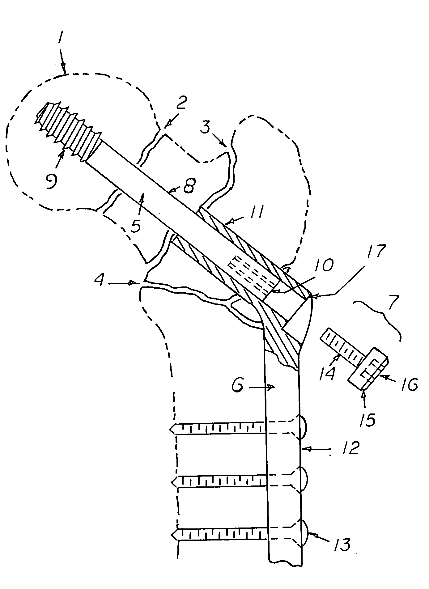
[0017]FIG. 1 shows a generic compression hip screw within a schematic representation of the proximal femur 1. Fracture patterns well controlled by a conventional hip screw include the femoral neck fracture 2, and the intertrochanteric hip fracture 3. The reverse obliquity hip fracture 4 is not well stabilized with a conventional compression hip screw and it is towards this fracture pattern, with or without comminuted extensions, that the Locking Compression Hip Screw is directed.

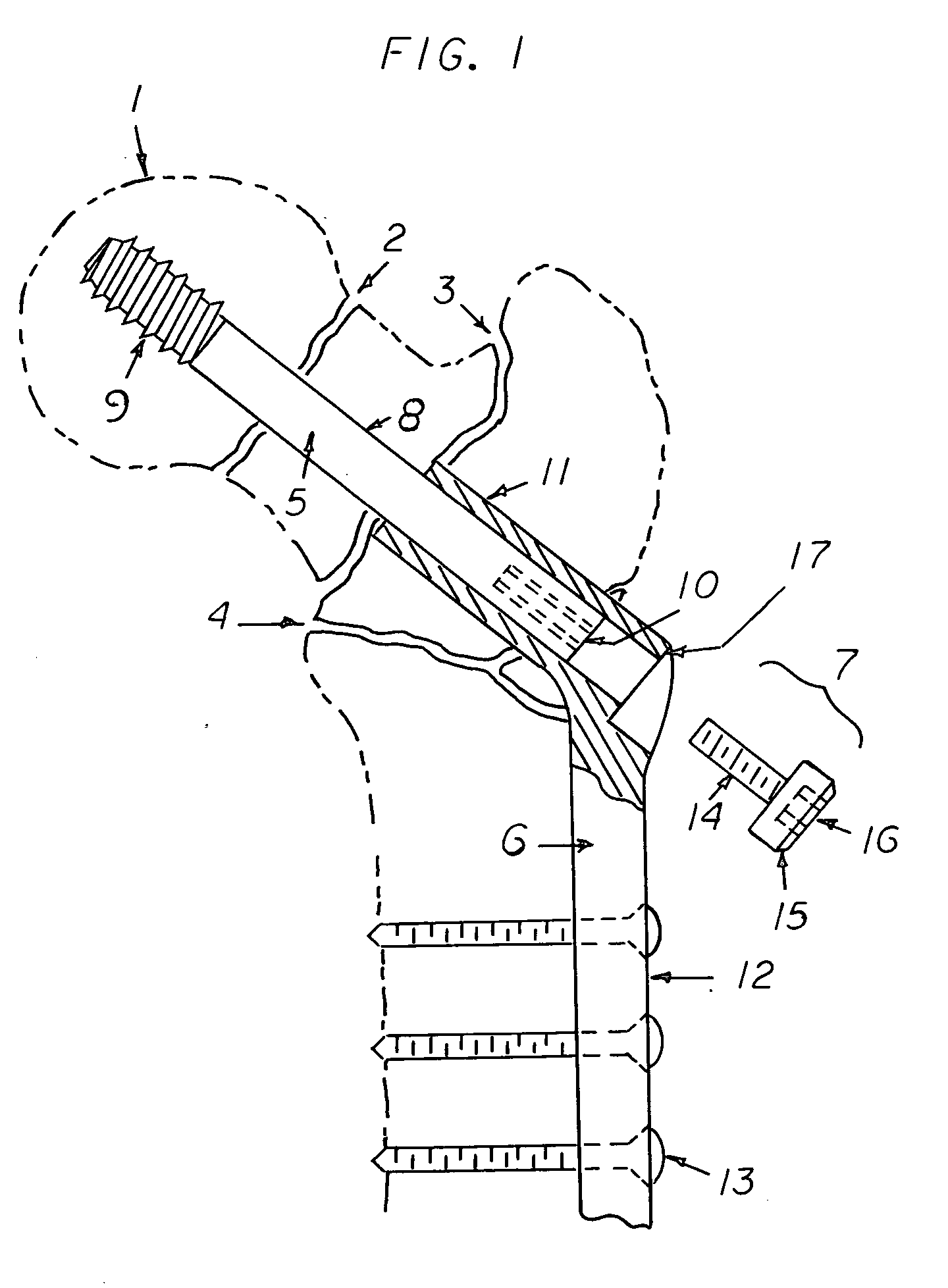
[0018] The three integral parts of a generic compression hip screw are: the femoral head lag screw 5, the side plate 6, and the compressing screw 7.

[0019] The femoral head lag screw consists of a smooth metallic shank 8 of variable length, with course cancerous bone threads 9 on the medial end and axially aligned female threads within the lateral end 10. The lateral end may also have a flat or slot milled on its surface so that a custom insertion tool (wrench) can gain torsional purchase on the lateral end...


PUM


Abstract

A modification to the prototypical compression (dynamic or sliding) hip screw is described which expands the utility and surgical indications of this frequently used fracture fixation device to include the fracture pattern commonly referred to as a “reverse obliquity fracture” of the proximal femur. This fracture pattern is poorly secured with current generation hip screws, frequently necessitating the use of intramedulary fracture fixation devices or external fixation hardware. The described modification blocks telescopic sliding of the femoral head lag screw within the cylindrical barrel of the side plate and allows for secure locking of the lag screw within the side plate, preventing any relative motion between the screw and plate once fracture reduction has been achieved. In a locked mode, the proximal fracture fragment(s) is prevented from displacing laterally relative to the distal (diaphysial) fragment, as occurs commonly when a reverse obliquity fracture or a comminuted intertrochanteric femur fracture is fixed with a conventional hip screw. No change in routine fracture reduction or insertion technique is required to use the Locking Compression Hip Screw. Additionally, the described modification does not preclude use of the Locking Compression Hip Screw in a dynamic or sliding mode, if desired, when used to fix the more common femoral neck or intertrochanteric fracture patterns.

Description

REFERENCES CITED [REFERENCED BY][0001]U.S. Patent Document4,432,358February 1984Fixel129 / 92 BB4,621,629August 1985Koeneman128 / 92 YS4,612,920September 1986Lower128 / 92 BA4,617,922October 1986Griggs128 / 92 YS4,657,001April 1987Fixel128 / 92 YS5,041,116August 1991Wilson606 / 655,167,663December 1992Brumfield606 / 645,324,292June 1994Meyers606 / 735,454,813October 1995Lawes606 / 625,032,125July 1999Durham606 / 626,443,954 B1September 2002Bramlet et al.606 / 626,645,209 B2November 2003Hall, IV et al.606 / 69ADDITIONAL REFERENCES [0002] 1. Cole, P. A. and Bhandari, M. “Specialty Update: What's new in Orthopaedic Trauma”. J Bone Joint Surg 87A (12), 2005; 2823-2838. [0003] 2. Shaw, J. A. and Wilson, S. “Internal Fixation of Proximal Femur Fractures: A Biomechanical Comparison of the Gamma Locking Nail and the Omega Compression Hip Screw”. Orthopedic Review 22 (1), 1993; 61-68. DESCRIPTION BACKGROUND OF THE INVENTION [0004] The compression hip screw (also referred to as a dynamic hip screw or sliding hip scr...

Claims


Application Information

Patent Timeline
IPC IPC(8): A61F2/30
CPCA61B17/746
Inventor SHAW, JAMES ALBERT
Owner SHAW JAMES ALBERT
Why Eureka
Try Eureka