
Emulation method and computer system

Active Publication Date: 2007-11-22
NEC PLATFORMS LTD
View PDF18 Cites 1 Cited by
  • Summary
  • Abstract
  • Description
  • Claims
  • Application Information

AI Technical Summary

Benefits of technology

[0011]Under such circumstances, it is an object of the present invention to provide an emulation method and a computer system capable of improving the emulation speed of a target system respectively.
[0015]According to the present invention, therefore, because plural target instructions can be processed collectively as described above, the emulation speed can be improved without adding any emulation-dedicated hardware to the base system.

Problems solved by technology

In the case of such an emulation method, however, the target system emulation speed depends significantly on how much the host system hardware performance is improved for executing each processing according to each target instruction; the emulation speed is not improved as long as the host system's hardware performance is not improved.
Among the above described conventional computer systems, the configuration of the computer system disclosed in JP 2004-127154 A confronts a problem that the system is expanded in scale, since some additional units are required to determine the number of processors, divide each emulation processing, assign a divided processing to each processor, and collect the processing result of each processor.
However, they do not quicken other processings.
Thus, both of the methods will not be effective so much to improve the emulation speed.

Method used


Image

  • Emulation method and computer system
  • Emulation method and computer system
  • Emulation method and computer system

Examples


embodiments

. EMBODIMENTS

[0041]Hereunder, the preferred embodiments of the present invention will be described with reference to the accompanying drawings.

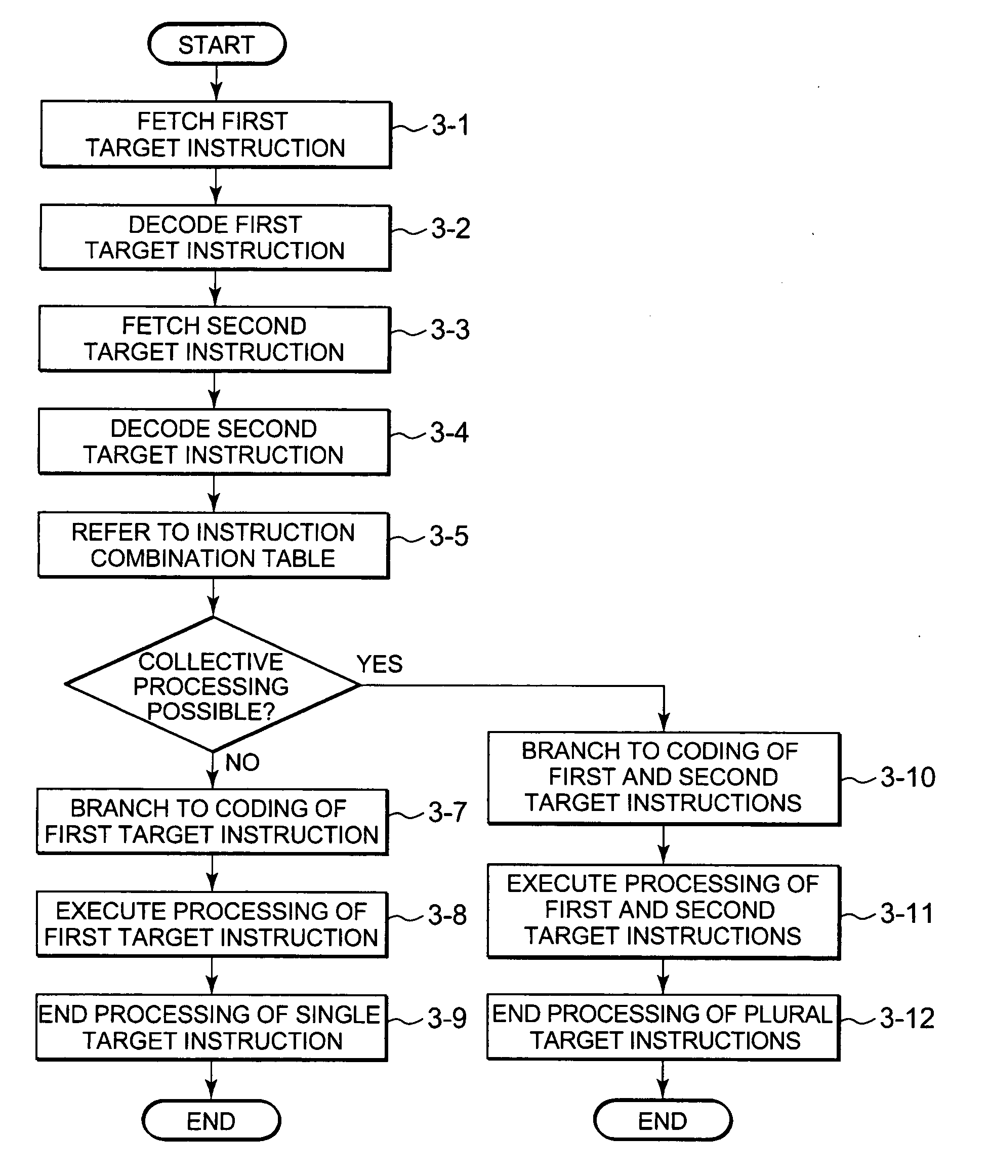
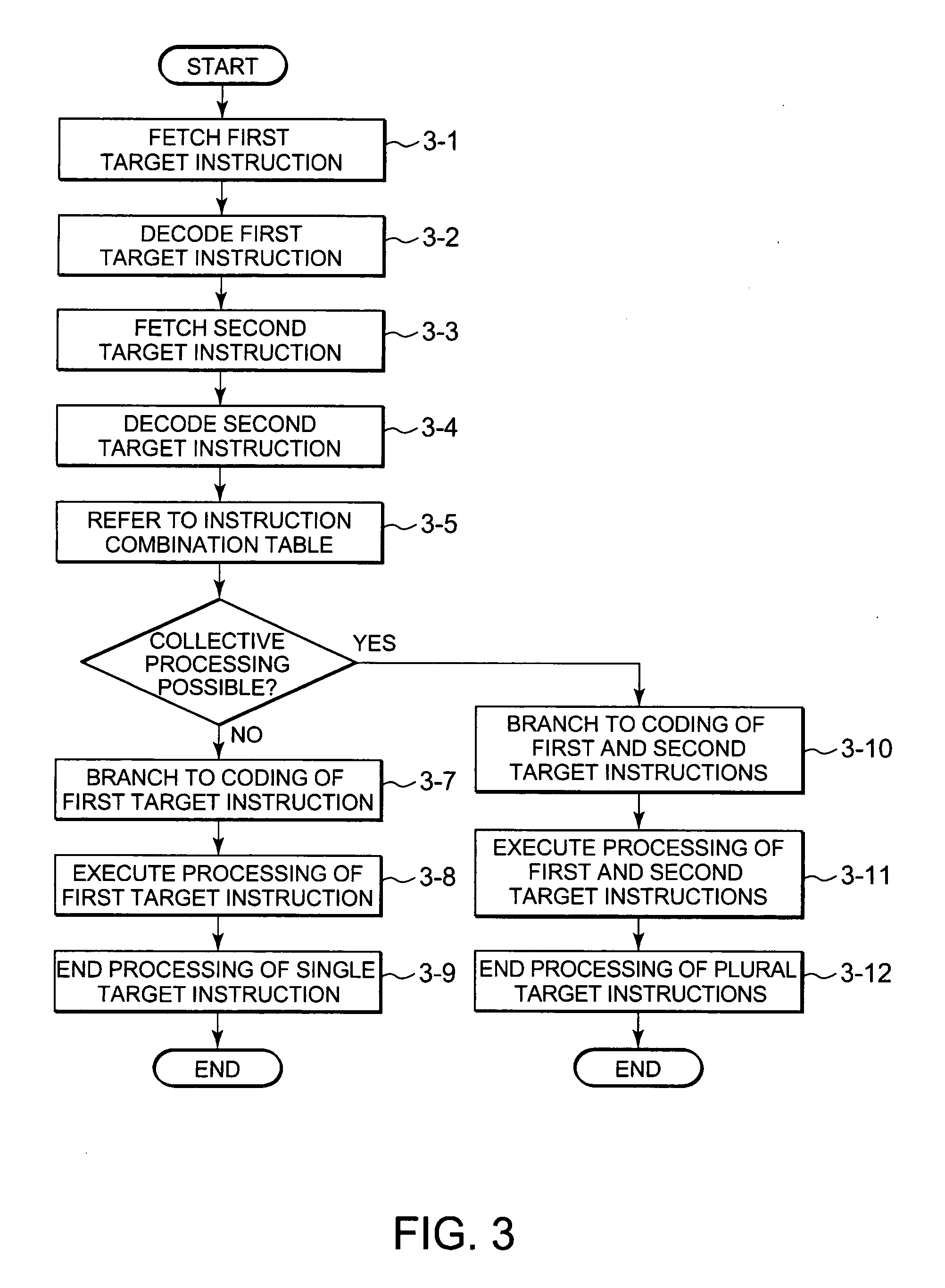
[0042]The computer system of the present invention includes an emulator (emulation program), which is provided with functions for processing plural target instructions collectively, thereby improving the emulation speed of the target system. Concretely, in case where plural target instructions to be processed collectively are combined for emulation, those target instructions, which are created beforehand, are branched to collective emulation coding and processed collectively according to the coding.

first embodiment

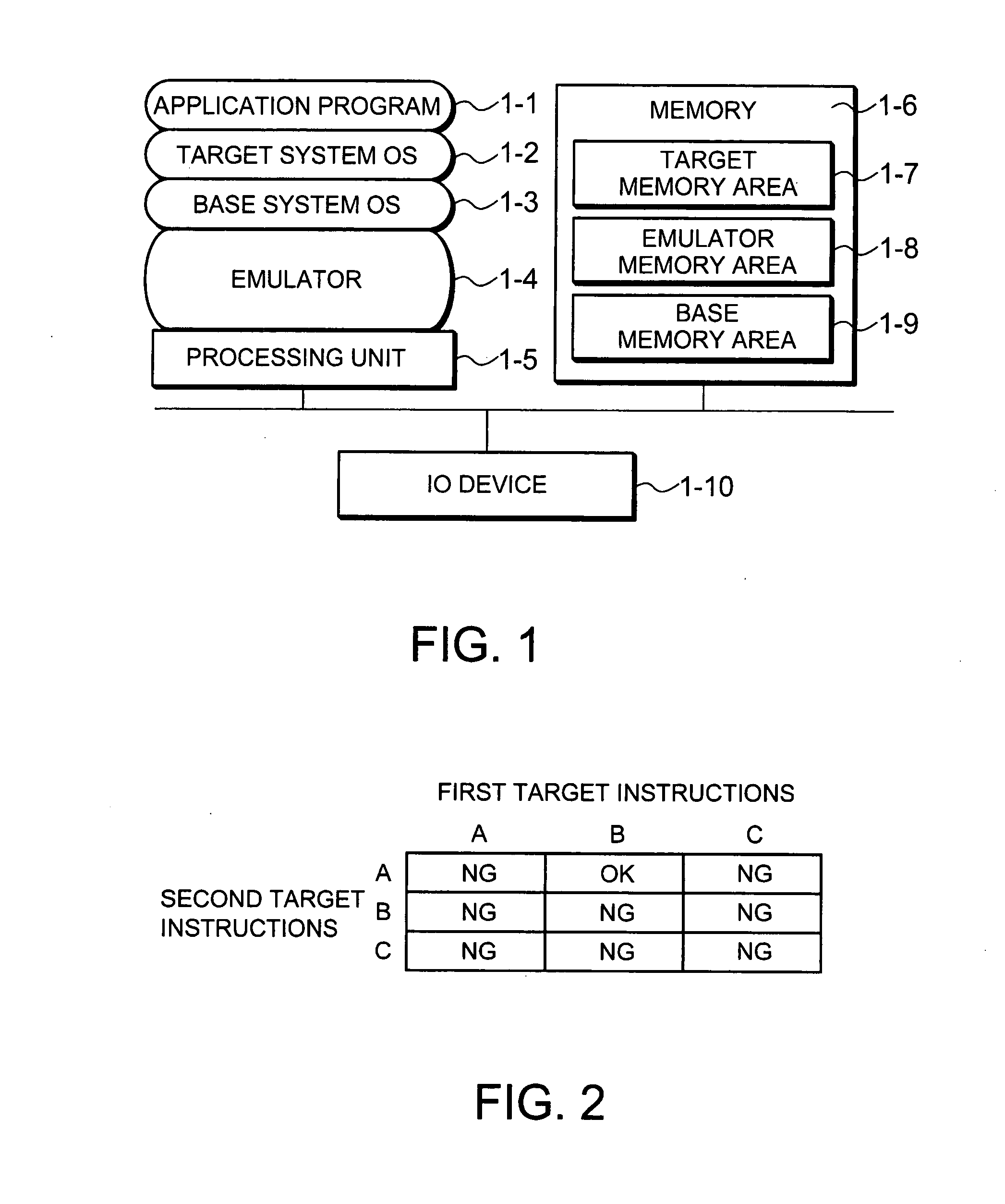
[0043]FIG. 1 shows a block diagram of a computer system of the present invention.

[0044]As shown in FIG. 1, the computer system of the present invention comprises a processing unit 1-5 that includes a processor (VCPU); a memory 1-6 for storing programs and information required for the processings of the processing unit 1-5; and an input device for inputting commands, information, etc. to the processing unit 5-1 or an IO device (Input Output), which is used to monitor results of processings of the processing unit 5-1.

[0045]The memory 1-6 includes a target memory area 1-7 for storing a target system OS; an emulator memory area 1-8 for storing an emulation program (emulator 1-4); and a base memory area 1-9 for storing a base system OS.

[0046]The memory 1-6 also stores an instruction combination table to be described later and a process branch table or instruction combination history table that are all used by an emulation method of the present invention. The memory 6-1 may be any of such...

second embodiment

[0073]Next, a computer system in a second embodiment of the present invention will be described with reference to the accompanying drawings.

[0074]The second embodiment aims at improving the emulation speed by using a process branch table instead of the instruction combination table used in the first embodiment. The computer system configuration is the same as that in the first embodiment, so that the description of the system configuration in this second embodiment will be omitted here.

[0075]As shown in FIG. 14, the process branch table stores process names denoting predetermined processes, instruction counters corresponding to those process names respectively, and information denoting coding branch destinations for processing plural target instructions collectively in the respective processes. The process names, instruction counters, and branch destinations are related at one-to-one-to-one correspondence.

[0076]FIG. 15 shows a concrete example of denoting each process name and an in...


PUM


Abstract

The computer system of the present invention emulates target instructions. The computer system includes a processing unit for branching to collective emulation coding for emulating plural of target instructions created beforehand collectively, thereby processing those instructions collectively according to the coding when those target instructions are combined so as to be processed collectively and a memory for storing the collective emulation coding.

Description

BACKGROUND OF THE INVENTIONFIELD OF THE INVENTION[0001]There are two well-known emulation methods for enabling another system (OS, CPU, or the like) to function on a base system; emulation by hardware and emulation by software. The present invention relates to the latter emulation method, that is, an emulation method by software, and a computer system.INCORPORATION BY REFERENCE[0002]This application is based upon and claims the benefit of priority from Japanese patent application No. 2006-137857, filed on May 17, 2006, the disclosure of which is incorporated herein in its entirety by reference.DESCRIPTION OF THE RELATED ART[0003]When realizing the functions of, for example, an OS of another system (hereinafter, to be referred to as a target system) on a base system, each of the conventional computer systems executes emulation for the instructions of a target system (hereinafter, to be referred to as target instructions) individually.[0004]FIG. 24 shows a flowchart of the processing ...

Claims


Application Information

Patent Timeline
IPC IPC(8): G06F9/455
CPCG06F9/45504
Inventor FUJIHARA, TSUTOMU
Owner NEC PLATFORMS LTD
Features
  • Generate Ideas
  • Intellectual Property
  • Life Sciences
  • Materials
  • Tech Scout
  • Unparalleled Data Quality
  • Higher Quality Content
  • 60% Fewer Hallucinations
Learn More