Attachment for a Cleaning Appliance

Inactive Publication Date: 2007-11-29
DYSON TECH LTD
View PDF0 Cites 7 Cited by
  • Summary
  • Abstract
  • Description
  • Claims
  • Application Information

AI Technical Summary

Benefits of technology

[0004] It is an object of the present invention to provide an attachment for a cleaning appliance which is economical to manufacture and which is unlikely to become stuck to any surf

Problems solved by technology

These can be expensive to manufacture and the bleed holes can also become blocked.
If tools or attachments are provided with a vacuum cleaner, the manufacturer fac

Method used


Image

  • Attachment for a Cleaning Appliance
  • Attachment for a Cleaning Appliance
  • Attachment for a Cleaning Appliance

Examples


Example

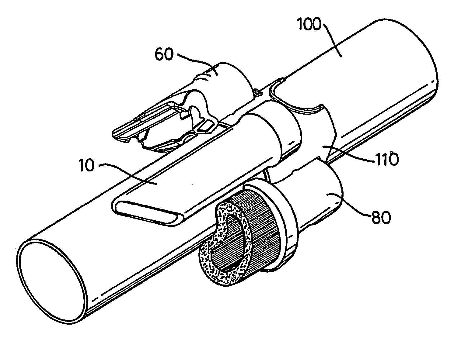
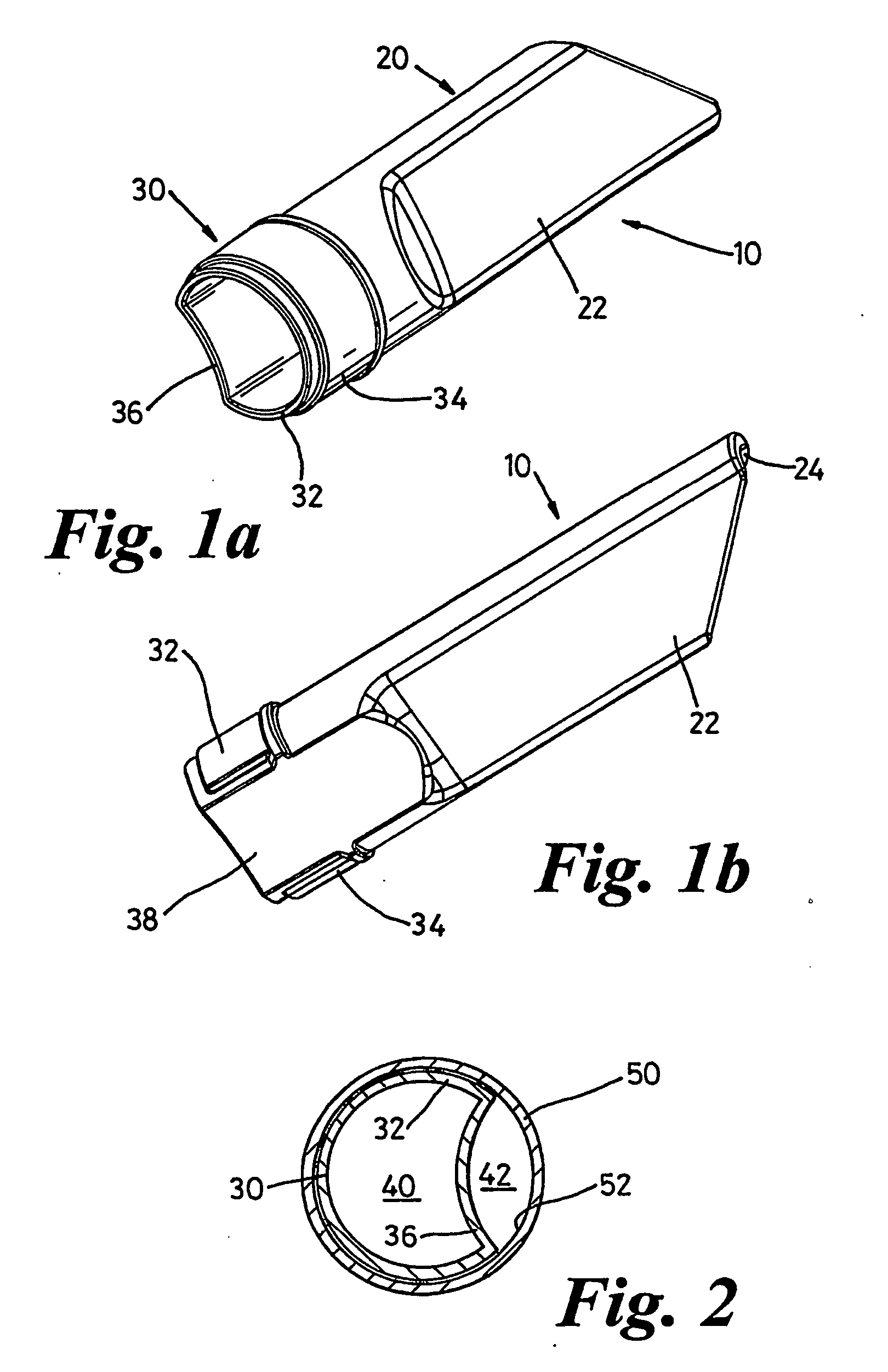
[0021] A first embodiment of an attachment according to the invention is shown in FIGS. 1a and 1b. The attachment takes the form of a crevice tool 10 which has a head 20 and a neck 30. The head 20 has an elongate body 22 with a suction opening 24 at the end remote from the neck 30. In the manner of known crevice tools, the elongate body 22 is relatively long and slender to allow access to areas of floor which are otherwise difficult to access, and the suction opening 24 lies in a plane which is inclined to the longitudinal axis of the elongate body 22.

[0022] The neck 30 is manufactured integrally with the head 20 and is adapted to cooperate with the end of a wand or hose of a cleaning appliance (not shown). The head 30 has a first portion 32 which comprises a part-cylindrical wall 34 extending axially away from the head 20. The outer surface of the part-cylindrical wall 34 is dimensioned so as to be capable of being inserted into the end of the wand or hose and retained therein by ...


PUM


Abstract

An attachment for a cleaning appliance includes a head and a neck, the neck being adapted to be connected to the mouth of a wand or hose of the cleaning appliance. The neck has a first portion which, in use, lies alongside the mouth of the wand or hose and a second portion which, in use, is spaced away from the mouth of the wand or hose. This arrangement provides a bleed air passageway which allows atmospheric air to be bled into the hose or wand so as to reduce the suction at the main suction opening of the attachment. It also provides an advantageous storage solution for the attachments of the cleaning appliance.

Description

FIELD OF THE INVENTION [0001] The invention relates to an attachment for a cleaning appliance particularly, but not exclusively, for a vacuum cleaner. The invention also provides a combination of an attachment holder and at least one attachment. The invention further provides a vacuum cleaner having at least one attachment. BACKGROUND OF THE INVENTION [0002] Attachments for vacuum cleaners are well known and are commonly provided by vacuum cleaner manufacturers to allow their products to be used for a wide variety of uses. For example, many vacuum cleaners are provided with stair tools for cleaning staircases, brush tools for dusting surfaces without scratching, and crevice tools for cleaning in small areas which are inaccessible using larger tools. These tools or attachments are normally connected to either a hose end or a wand of the vacuum cleaner with which they are to be used by means of a simple friction fit between the cylindrical hose end or wand and the cylindrical neck of ...

Claims


Application Information

Patent Timeline
IPC IPC(8): A47L9/06A47L9/00A47L9/02
CPCA47L9/0009A47L9/02A47L9/0027A47L9/00
Inventor ADAMS, PAUL MICHAEL
Owner DYSON TECH LTD
Why Eureka
Try Eureka