Assembly for collecting material entrained in a gas stream

a technology of gas stream and collection layer, which is applied in the direction of cartridge filter, dispersed particle filtration, liquid separation agent, etc., can solve the problems of reentrainment of contaminants in the gas stream, limited life of the element used in such filtration, etc., and achieve the effect of increasing the surface area increasing the rigidity of the filtration layer

Active Publication Date: 2007-11-29
PARKER HANNIFIN LTD HEMEL HEMPSTEAD
View PDF16 Cites 27 Cited by
  • Summary
  • Abstract
  • Description
  • Claims
  • Application Information

AI Technical Summary

Benefits of technology

[0083] Materials suitable for use in a filtration filter element will be selected according to the nature of the gas that is being filtered, the nature of the contaminants (liquid droplets, aerosols, solid particles etc) to be filtered from the gas, the pressure differential across the filter and so on. Such materials are known, including those used by Domnick Hunter Limited in products which are available under the trade mark OIL-X. Suitable materials for use as a filtration medium (or a filtration layer) include, borosilicate and other glass fibers, activated carbon minerals, activated silica materials and so on. A filtration layer can be made from woven fibers. However, as will be appreciated, a filtration layer can be made from sheets of non-woven fibers. For example, a microfiber filtration layer made from fine organic or inorganic fibers is preferred. Preferably, a coarser fiber layer is fitted on the inside of a microfiber filtration layer. This coarser layer can protect a microfiber filtration layer from gross pollution.
[0084] Preferably, the filtration layer can comprise a layer of a material which has been folded so that it is fluted (or pleated). This can increase the surface area of the filtration layer through which air flowing through the filter element will pass. This can also help to increase the rigidity of the filtration layer.

Problems solved by technology

A filter element used for such filtration has a limited lifetime: accumulation of contaminants with prolonged use gives rise to unacceptable pressure drop, and can also lead to reentrainment of the contaminants in the gas stream.

Method used


Image

  • Assembly for collecting material entrained in a gas stream
  • Assembly for collecting material entrained in a gas stream
  • Assembly for collecting material entrained in a gas stream

Examples


Embodiment Construction

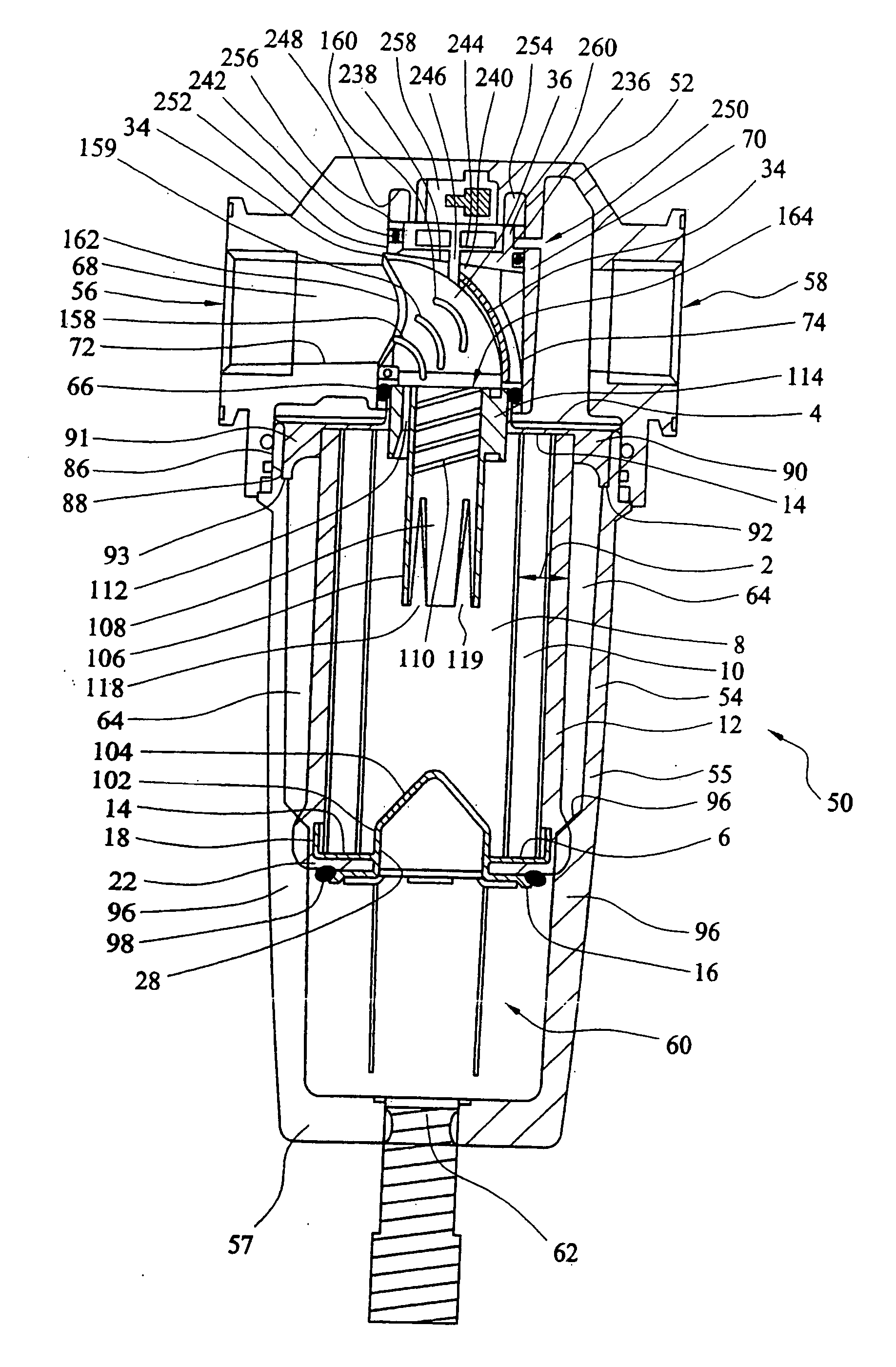
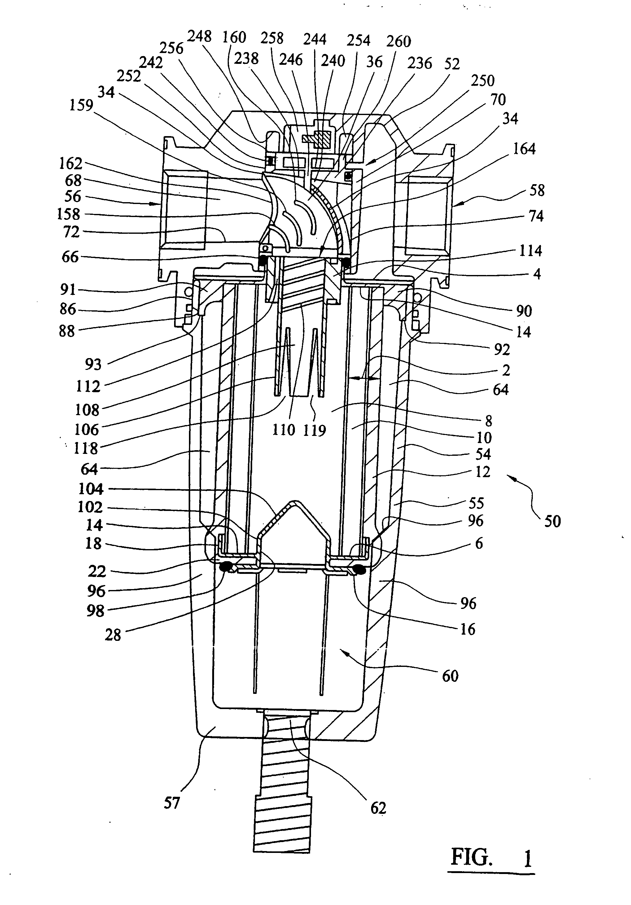
[0140] Referring to the drawings, FIGS. 1 to 18 illustrate one embodiment of an assembly for removing material entrained in a gas stream according to the present invention. The assembly shown is a filter assembly which utilizes a filtration medium to remove the material from the gas stream. As will be appreciated, other types of assemblies according to the present invention can be utilized for removing material entrained in a gas stream, such as a separator assembly as described below with reference to FIGS. 19 to 24.

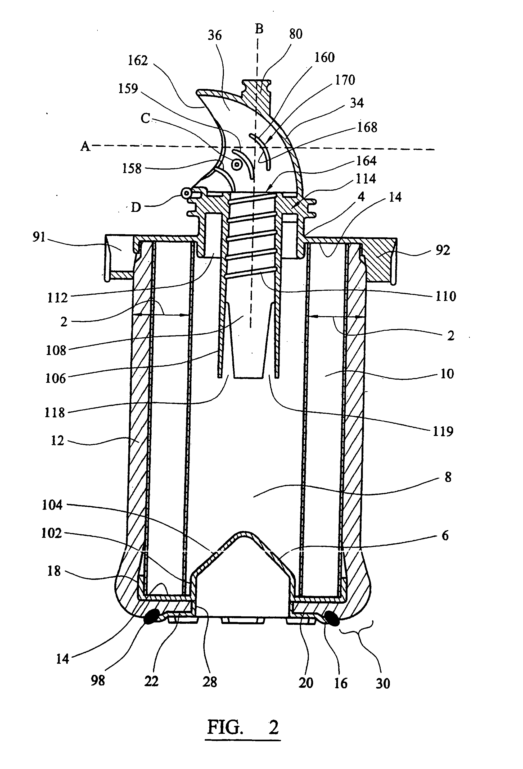
[0141]FIG. 2 shows a filter element which comprises a cylindrical wall section 2 formed from a filter medium and top and bottom end caps 4 and 6.

[0142] The wall section 2 defines a hollow space 8 within it. The filter medium of the wall 2 comprises a cylindrical filtration layer 10 and a cylindrical anti-reentrainment layer or drainage layer 12 which fits snugly around the filtration layer on the outside of the filter element.

[0143] The top end cap 4 contains a flow ...


PUM

PropertyMeasurementUnit
angleaaaaaaaaaa
angleaaaaaaaaaa
angleaaaaaaaaaa

Abstract

An assembly for collecting material entrained in a gas stream comprising a housing having a head part and a body part, and inlet and outlet ports. A chamber port is provided in the head part having internal walls defining a primary chamber with a first end communicating with the chamber port and an opening at a second end. The axis of the first and second ends of the primary chamber are non-aligned. A flow conduit device has a first end which can fit into the primary chamber in the housing head part so that it is directed generally towards the chamber port in the housing and a second end which is directed towards the body part of the housing to provide a conduit for gas to flow between the body part of the housing and the outlet port. The flow conduit reduces turbulence in the flow of gas within the chamber.

Description

CROSS REFERENCE TO RELATED APPLICATIONS [0001] This application is continuation of copending International Application No. PCT / GB05 / 002948 filed Jul. 26, 2005, which designated the United States, the disclosure of which is incorporated herein by reference, and which claims priority to Great Britain Patent Application 0417458.7, filed Aug. 5, 2004.BACKGROUND OF THE INVENTION [0002] This invention relates to an assembly for collecting material entrained in a gas stream. SUMMARY OF THE INVENTION [0003] Material entrained in a gas stream can be collected and removed from the gas stream flow using many different methods. For example, material entrained in a gas stream can be collected and removed through imparting centrifugal forces on the material by spinning the gas stream, or by passing the gas stream through a filtration medium which removes the material as the gas flows through it. [0004] Removal of material from a gas stream can be required to ensure that the gas is sufficiently cl...

Claims


Application Information

Patent Timeline
Patent Type & Authority Applications(United States)
IPC IPC(8): B01D46/00B01D46/24B01D53/26
CPCB01D46/0012B01D46/0031B01D46/0045B01D46/2414B01D2275/10B01D2201/295B01D2201/302B01D2271/02B01D53/266
Inventor PEARSON, JOHNBITTLE, THOMAS STEPHENTROWSDALE, RAYMOND FRANCISLANE, BRIAN
Owner PARKER HANNIFIN LTD HEMEL HEMPSTEAD
Why Eureka
Try Eureka