Angular rate sensor

a technology of angular rate and sensor, which is applied in the direction of acceleration measurement using interia forces, turn-sensitive devices, instruments, etc., can solve the problems of not always being able to utilize the entire coriolis force component as the detected vibration torque, and it is difficult to align the resonant frequency between the two oscillators. , to achieve the effect of increasing the detected vibration, reducing noise, and large vibration

Inactive Publication Date: 2007-11-29
HITACHI METALS LTD
View PDF9 Cites 25 Cited by
  • Summary
  • Abstract
  • Description
  • Claims
  • Application Information

AI Technical Summary

Benefits of technology

[0013] According to the angular rate sensor of the present invention, the first detecting oscillator and the second detecting oscillator vibrate in mutually reversed phases in a direction of a third axis perpendicular to the plane of the sensor element as the rotating oscillator rotationally vibrates around the rotational axis. Thereby, detected vibration in the direction of the second axis is also converted into a reversed phase. Thus, it is possible to cancel detection signals in the same phase caused by acceleration in the direction of the second axis by finding the difference between detection signals outputted by the respective first and second detecting units, and thereby to reduce noises. Moreover, the first and second detecting oscillators are disposed inside the single rotating oscillator, and driving vibration in the direction of the third axis is given by the vibration of the rotating oscillator. Accordingly, it is structurally guaranteed that the amplitudes of the vibrations of both of the detecting oscillators coincide with each other, and the reversal of the phases. By driving the rotating oscillator by use of a resonant frequency, it is possible to align the amplitudes and to obtain large vibration. Thereby, it is made possible to increase the detected vibration, and to achieve high detection sensitivity. In addition, by disposing the detecting oscillators farther from the rotational axis while disposing the detecting units closer to the rotational axis, it is possible to increase the amplitudes of the detecting oscillators more than those of the respective detecting units for the same rotation-angle amplitude. Hence, it is possible to improve the detection sensitivity, and to reduce driving amplitudes of the detecting units (vibration amplitudes in the direction of the third axis). In this way, it is possible to reduce an influence of the driving vibration applied to the detection of the detected vibration in the direction of the second axis, and thereby to reduce noises.

Problems solved by technology

However, due to problems of fabrication accuracy and so forth, it is difficult to align resonant frequencies between the two oscillators.
However, the configuration and control operations in the configuration are made complicated with the added resonant-frequency adjustment mechanism, and there is still room for improvement by simplifying the structure and facilitating the control operations.
For this reason, it is not always possible to utilize the entire Coriolis force component as the detected vibration torque.

Method used


Image

  • Angular rate sensor
  • Angular rate sensor
  • Angular rate sensor

Examples


Embodiment Construction

[0023] The preferred embodiments of the present invention will be described below with reference to the accompanying drawings. It is to be noted that the same reference numerals designated in the drawings for the embodiments indicate identical or equivalent constituents.

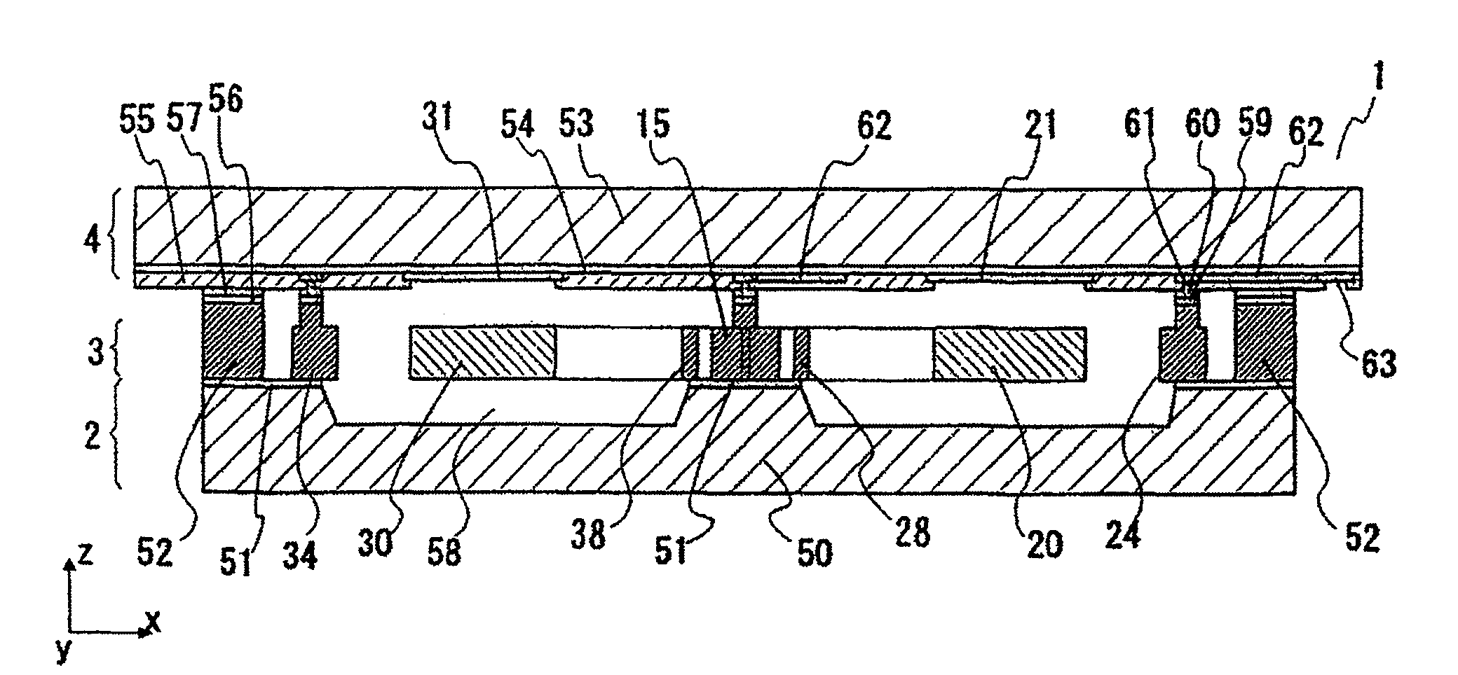
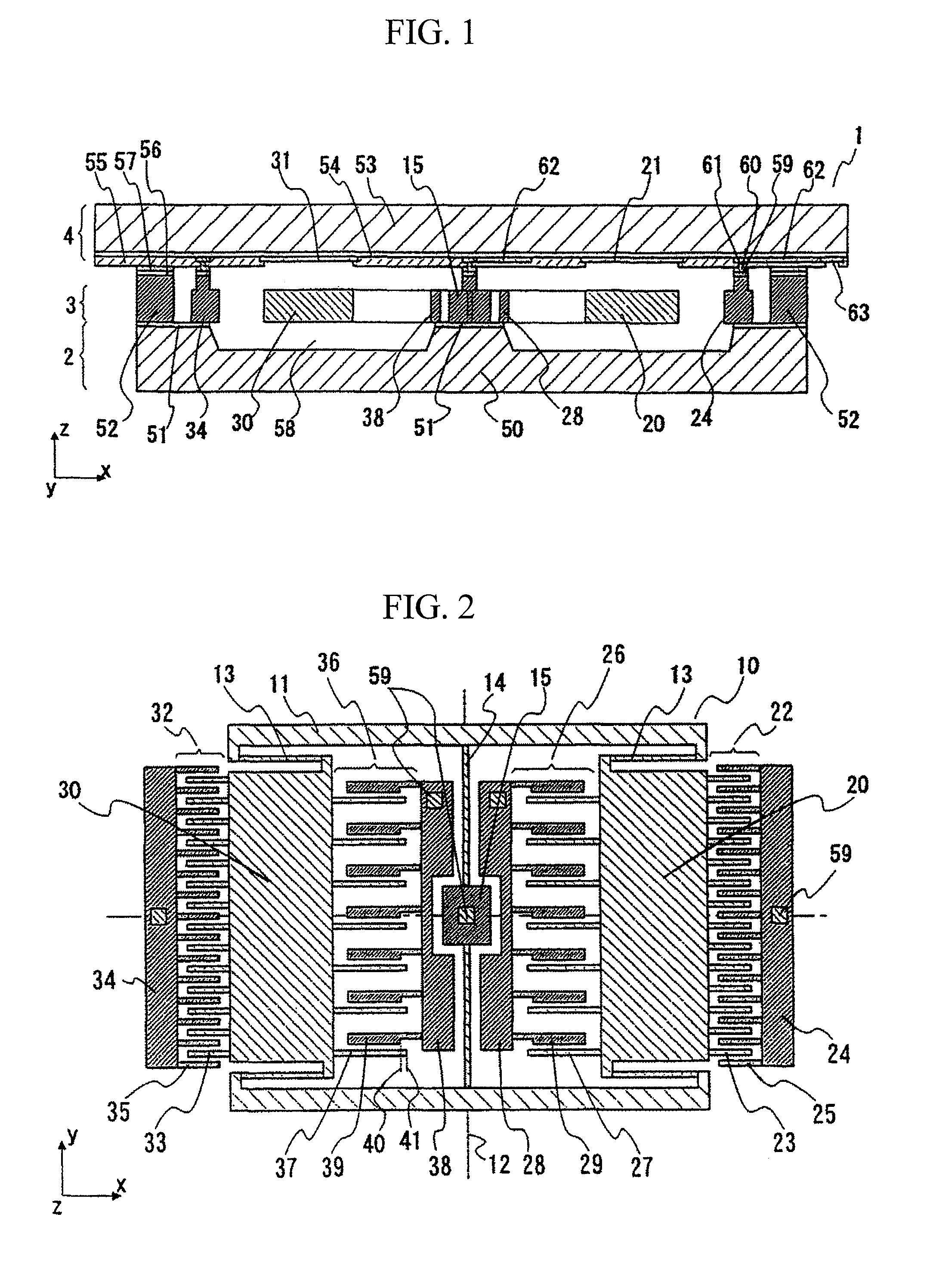
[0024] An angular rate sensor according to a first embodiment of the present invention will be described with reference to FIGS. 1 to 3. FIG. 1 is a cross-sectional view of this embodiment, and FIG. 2 is a schematic plan view of an element substrate of this embodiment.

[0025] As shown in FIG. 1, an angular rate sensor 1 of this embodiment includes three layers of a support substrate 2, an element substrate 3 and a wiring substrate 4. A movable portion of the sensor is formed inside the element substrate 3, and the structure inside the element substrate 3 includes a portion bonded and fixed to the support substrate 2, and another portion separated from the support substrate 2 and displaceably supported inside the ele...


PUM


Abstract

An angular rate sensor formed into a planar shape, which detects an angular rate around a first axis in the plane, includes a rotating oscillator rotatably supported in the plane and around the rotational axis in a direction of a second axis perpendicular to the first axis; vibration generating means which rotationally vibrates the rotating oscillator; and a first detecting oscillator and a second detecting oscillator which are disposed inside the rotating oscillator and separately on the right side and the left side of the rotational axis, and which are supported as being displaceable in a direction of the second axis. A first detecting unit and a second detecting unit, which detect vibrations of the respective first and second detecting oscillators in the direction of the second axis due to the Coriolis force, are respectively provided closer to the rotational axis than the first and second detecting oscillators are.

Description

BACKGROUND OF THE INVENTION [0001] 1. Field of the Invention [0002] The present invention relates to a small sensor for detecting an angular rate. [0003] 2. Description of the Related Art [0004] In recent years, researches for fabricating mass-producible small acceleration sensors by using silicon substrates and the like for a material, and by adapting the semiconductor manufacturing techniques, are actively pursued in the field of microelectromechanical systems (MEMS) as the techniques for achieving angular rate sensors (gyroscope sensors). [0005] The mainstream of the above-mentioned techniques is called vibration gyroscope. When a direction of the rotational axis of an angular rate to be measured is defined as a first axis, the vibration gyroscope causes an oscillator to vibrate in a direction of a second axial which is perpendicular to the first axis (driving vibration), and then vibration (detected vibration) due to the Coriolis force which is generated in a direction of a thir...

Claims


Application Information

Patent Timeline
Patent Type & Authority Applications(United States)
IPC IPC(8): G01P9/02G01P9/04G01P1/04G01C19/02G01C19/56G01C19/5712G01C19/574
CPCG01C19/5712G01P2015/0814G01P15/125G01P15/12
Inventor KAZAMA, ATSUSHINAKAMURA, SHIGEO
Owner HITACHI METALS LTD
Why Eureka
Try Eureka