Apparatus for controller-integrated motor

a controller and motor technology, applied in the direction of windings, magnetic circuit rotating parts, magnetic circuit shapes/forms/construction, etc., can solve the problems of loss of stators, temperature rise, need for periodic maintenance, etc., and achieve the effect of increasing cooling efficiency and reducing the axial width of shafts

Inactive Publication Date: 2007-11-29
KK TOSHIBA
View PDF4 Cites 83 Cited by
  • Summary
  • Abstract
  • Description
  • Claims
  • Application Information

AI Technical Summary

Benefits of technology

[0013]An object of the present invention is to provide a controller-integrated motor provided in a vehicle and which enables a reduction in the axial width of a shaft and an increase in cooling efficiency for the motor main body and the controller.

Problems solved by technology

The temperature rise is caused by a copper loss in stator and rotator windings, an iron loss in the stator, and other mechanical losses.
Consequently, dust may enter the motor, resulting in the need for periodic maintenance.
However, fully enclosed type traction motors with outer fans achieve a lower cooling efficiency than open type traction motors.
The fully enclosed type traction motor with the outer fan is limited in cooling capability even if the traction motor is separated from the controller.
However, a cooling structure in the above conventional controller-integrated motor has the following problems to be solved.
The railway vehicle is narrow in the width direction, limiting the space in which the motor can be installed.
Consequently, this motor reduces the degree of the freedom with which a motor installation position in the vehicle can be selected.
However, the increased capacity of the motor may prevent cooling from being achieved only by natural convection.

Method used


Image

  • Apparatus for controller-integrated motor
  • Apparatus for controller-integrated motor
  • Apparatus for controller-integrated motor

Examples


first embodiment

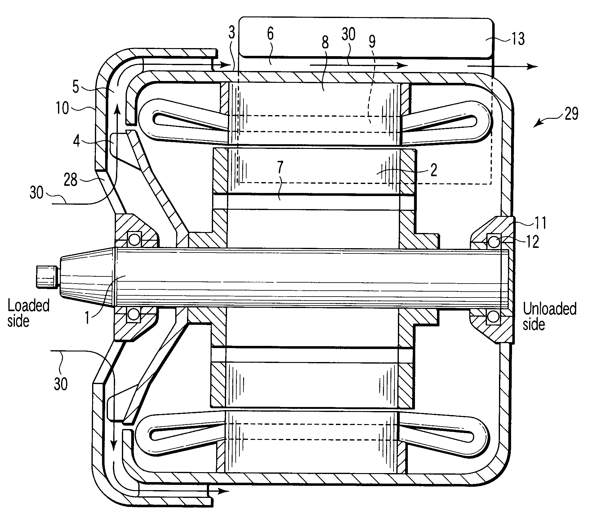
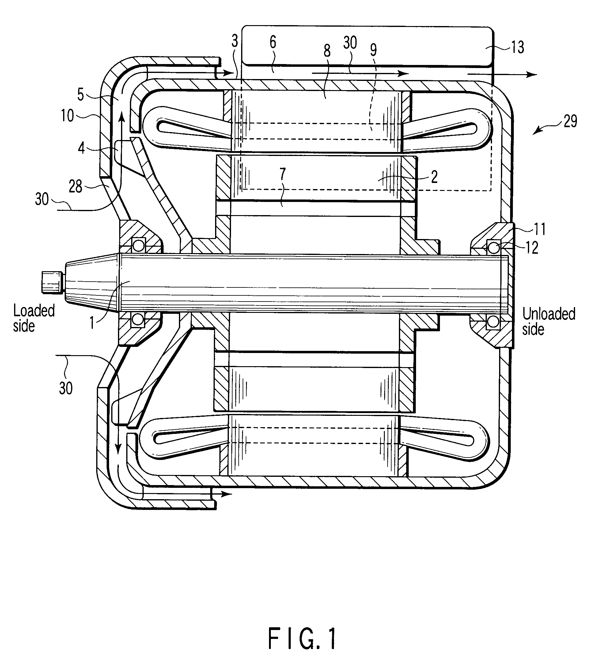
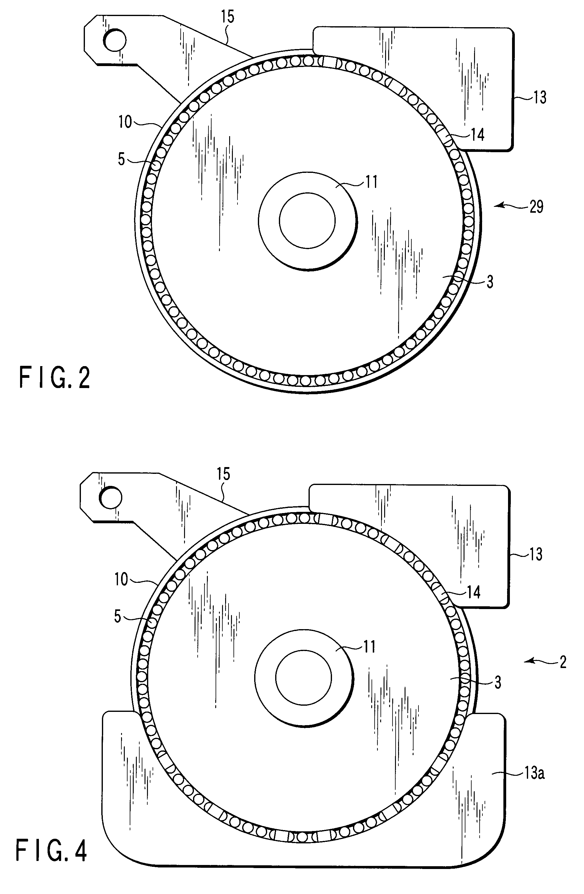
[0035]FIG. 1 is a vertical sectional view of a controller-integrated motor in accordance with a first embodiment of the present invention. FIG. 2 is a sectional view of an unloaded side of the controller-integrated motor in accordance with the first embodiment of the present invention. The same components in FIGS. 17, 1, and 2 are denoted by the same reference numerals and will not be described in detail. Different components will be mainly described. Duplicate descriptions are also omitted in the subsequent embodiments.

[0036]The present controller-integrated motor comprises a motor main body 29 and a controller 13 mounted on the motor main body 29. The motor main body 29 comprises a frame 3, an end plate 10, a stator core 8, a stator coil 9, a rotor core 2, a shaft 1 that rotates to exert driving force on the motor main body 29, and an outer fan 4 that discharges a cooling air stream 30 to cool the motor main body 29.

[0037]In the motor main body 29, the outer fan 4 is fittingly mou...

second embodiment

[0042]FIG. 3 is a vertical sectional view showing the configuration of a controller-integrated motor in accordance with a second embodiment of the present invention. FIG. 4 is a sectional view showing the configuration of an unloaded side of the controller-integrated motor in accordance with the second embodiment of the present invention.

[0043]An upper controller 13 and a lower controller 13a are installed in the present controller-integrated motor. An electric circuit in the controller 13 is connected to an electric circuit in the controller 13a. The connected electric circuits in the controllers 13 and 13a function as one controller. The controller comprising the combination of the controllers 13 and 13a controls the motor main body 29. The remaining part of the configuration is the same as that of the first embodiment.

[0044]The flow of the cooling air stream 30 in the present controller-integrated motor is similar to that in the first embodiment. Accordingly, the cooling air stre...

third embodiment

[0046]FIG. 5 is a perspective view showing the configuration of a controller provided in a controller-integrated motor in accordance with a third embodiment of the present invention.

[0047]The controller-integrated motor in accordance with the present embodiment is configured similarly to those in accordance with the first and second embodiments except for the controller.

[0048]The present controller-integrated motor has traveling air stream radiation fins 16 and cooling air stream radiation fins 17 on the surface of the controller 13.

[0049]The traveling air stream radiation fins 16 are installed laterally to the motor main body 29 (perpendicularly to the shaft 1) so as to allow a traveling air stream 31 resulting from the motion of the vehicle to flow smoothly. The traveling air stream radiation fins 16 are preferably long but do not interfere with the other components located around the motor main body 29.

[0050]The cooling air stream radiation fins 17 are installed in a vertical dir...


PUM


Abstract

A controller-integrated motor includes a motor main body and a controller integrated with the motor main body to control the motor main body, the motor main body, including a stator core, a shaft which rotates to exert driving force on the motor main body, a frame which holds the stator core and the shaft, and an outer fan provided around the shaft so that the motor main body is recessed inward toward a rotational center of the shaft, the outer fan discharging cooling air stream to cool the motor main body, the controller being provided in proximity to an outer periphery of the frame, the motor main body being formed so that a cooling air stream from the outer fan flows in an axial direction of the shaft along an outer peripheral surface of the frame.

Description

CROSS-REFERENCE TO RELATED APPLICATIONS[0001]This application is based upon and claims the benefit of priority from prior Japanese Patent Application No. 2006-134084, filed May 12, 2006, the entire contents of which are incorporated herein by reference.BACKGROUND OF THE INVENTION[0002]1. Field of the Invention[0003]The present invention relates to a controller-integrated motor includes a motor mainly used to drive a vehicle and a controller integrated with the motor to control the motor.[0004]2. Description of the Related Art[0005]Traction motors for vehicles are subjected to a temperature rise in each of their sections while the vehicle is in motion. The temperature rise is caused by a copper loss in stator and rotator windings, an iron loss in the stator, and other mechanical losses. The traction motor commonly uses the following scheme to cool itself. There is provided a blower that takes in external air to forcibly discharge an air stream into the motor. A fan is provided in the...

Claims


Application Information

Patent Timeline
Patent Type & Authority Applications(United States)
IPC IPC(8): H02K9/00H02K9/06H02K3/24
CPCH02K5/20H02K11/0073H02K9/14H02K9/06H02K11/33H02K5/203H02K5/207
Inventor KOYAMA, TAIHEINODA, SHINICHITONOKI, KENZOSHIRAISHI, SHIGETOMO
Owner KK TOSHIBA
Why Eureka
Try Eureka