Electrical machine with part-winding circuit

a technology of winding circuit and electric machine, which is applied in the direction of winding, polyphase induction motor starter, continuous variable inductance/transformer, etc., can solve the problems of increasing the cost of motor driving and asymmetric field distribution

a technology of winding circuit and electric machine, which is applied in the direction of winding, polyphase induction motor starter, continuous variable inductance/transformer, etc., can solve the problems of increasing the cost of motor driving and asymmetric field distribution

US20070273236A1Inactive Publication Date: 2007-11-29SIEMENS AG

Image

  • Electrical machine with part-winding circuit
  • Electrical machine with part-winding circuit
  • Electrical machine with part-winding circuit

Examples


Embodiment Construction

[0022] Throughout all the Figures, same or corresponding elements may generally be indicated by same reference numerals. These depicted embodiments are to be understood as illustrative of the invention and not as limiting in any way. It should also be understood that the figures are not necessarily to scale and that the embodiments are sometimes illustrated by graphic symbols, phantom lines, diagrammatic representations and fragmentary views. In certain instances, details which are not necessary for an understanding of the present invention or which render other details difficult to perceive may have been omitted.

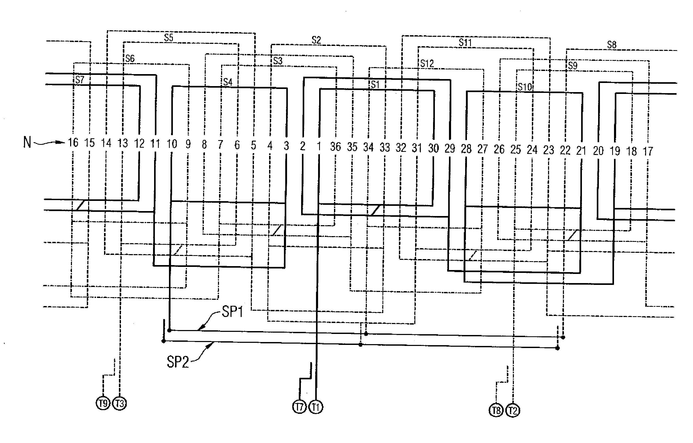
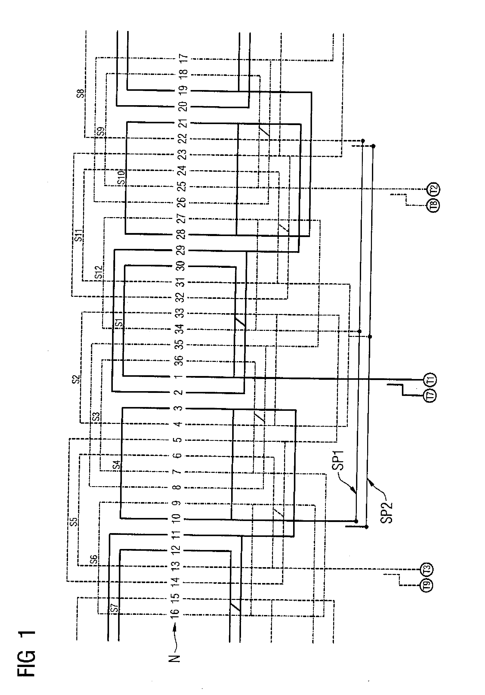
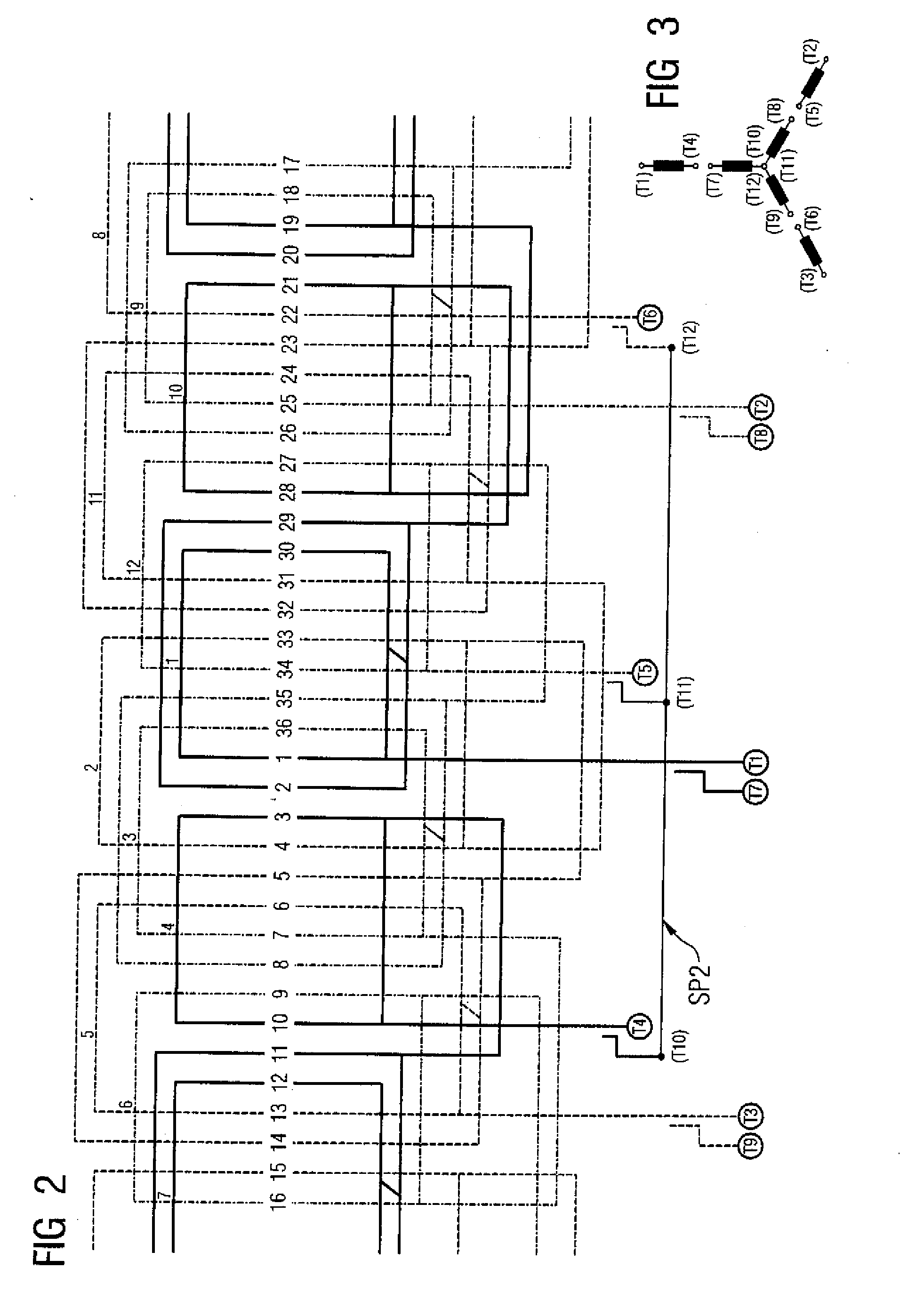
[0023] Turning now to the drawing, and in particular to FIG. 1, there is shown a four-pole winding which includes 12 coils S1 to S12, which are inserted or wound into 36 slots N. The coils S1, S4, S7 and S10 belong to a first phase and are illustrated by continuous lines in FIG. 1. The coils S3, S6, S9 and S12 belong to a second phase and are illustrated by dash-dotted lin...


PUM

PropertyMeasurementUnit
operating voltageaaaaaaaaaa
currentaaaaaaaaaa

Abstract

An electrical machine includes a first part-winding, a second part-winding, a core having slots in which the first and the second part-windings are wound, and a switching device for connecting the first part-winding to the second part-winding. In each of the slots, one of the two part-windings forms a bottom layer at the slot base, and the other part-winding is disposed as a top layer parallel above the bottom layer. The two part-windings are capable of being connected in parallel with the switching device during operation of the electrical machine. It is thus possible for a symmetrical field distribution to be achieved in a startup circuit. In addition, no additional components caused by harmonic fields occur in the torque curve which could impede runup.

Description

CROSS-REFERENCES TO RELATED APPLICATIONS [0001] This application claims the priority of German Patent Application, Serial No. 10 2006 024 241.6, filed May 23, 2006, pursuant to 35 U.S.C. 119(a)-(d), the content of which is incorporated herein by reference in its entirety as if fully set forth herein. BACKGROUND OF THE INVENTION [0002] The present invention relates, in general, to the field of electrical machines [0003] Nothing in the following discussion of the state of the art is to be construed as an admission of prior art. [0004] An electric machine of a type involved here includes a first part-winding, a second part-winding, a core having slots in which the first and the second part-windings are wound, and a switching device for connecting the first part-winding to the second part-winding. In the following description, the term “part-winding” relates to a winding unit which, optionally including a plurality of turns, can be connected to a winding head of the electric machine. [0...

Claims


Application Information

Patent Timeline
29 Nov 2007
Publication
US20070273236A1
IPC
H02K3/00; H01F27/28
CPC
H02K3/28; H02P25/16; H02P1/26
Inventors
KAUMANN, ULRICH; LYSCHICK, EDUARD