
Transformerless Utility-Grid-Interactive Inverter

a transformer and utility grid technology, applied in the direction of electric variable regulation, process and machine control, instruments, etc., can solve the problems of high current means, higher component cost, higher cost, weight and loss of transformer b>30/b>, and the effect of increasing the current of the transformer

Inactive Publication Date: 2007-11-29
SCHNEIDER ELECTRIC SOLAR INVERTERS USA
View PDF7 Cites 61 Cited by
  • Summary
  • Abstract
  • Description
  • Claims
  • Application Information

AI Technical Summary

Problems solved by technology

There are two major drawbacks to this approach.
Higher current means higher losses and higher component costs.
Second, the cost, weight and losses associated with transformer 30 are significant.
The automatic circuitry required to provide this nighttime transformer function increases cost and complexity.
The drawback with this topology is that all of the throughput power must be processed twice, once by the DC-to-DC boost circuits and once by bridge 60.
This double conversion limits the power conversion efficiency of the system.

Method used


Image

  • Transformerless Utility-Grid-Interactive Inverter
  • Transformerless Utility-Grid-Interactive Inverter
  • Transformerless Utility-Grid-Interactive Inverter

Examples


Embodiment Construction

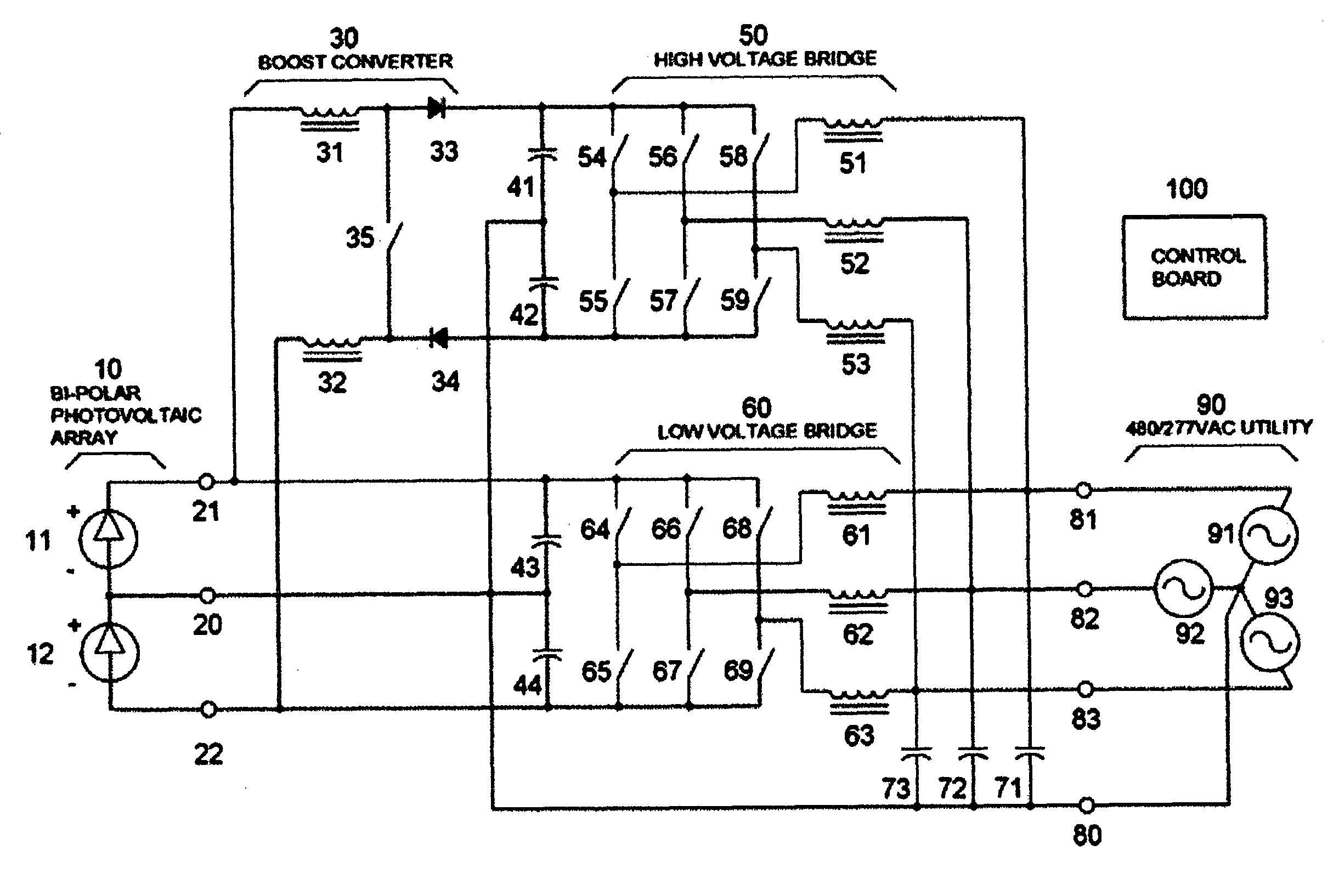
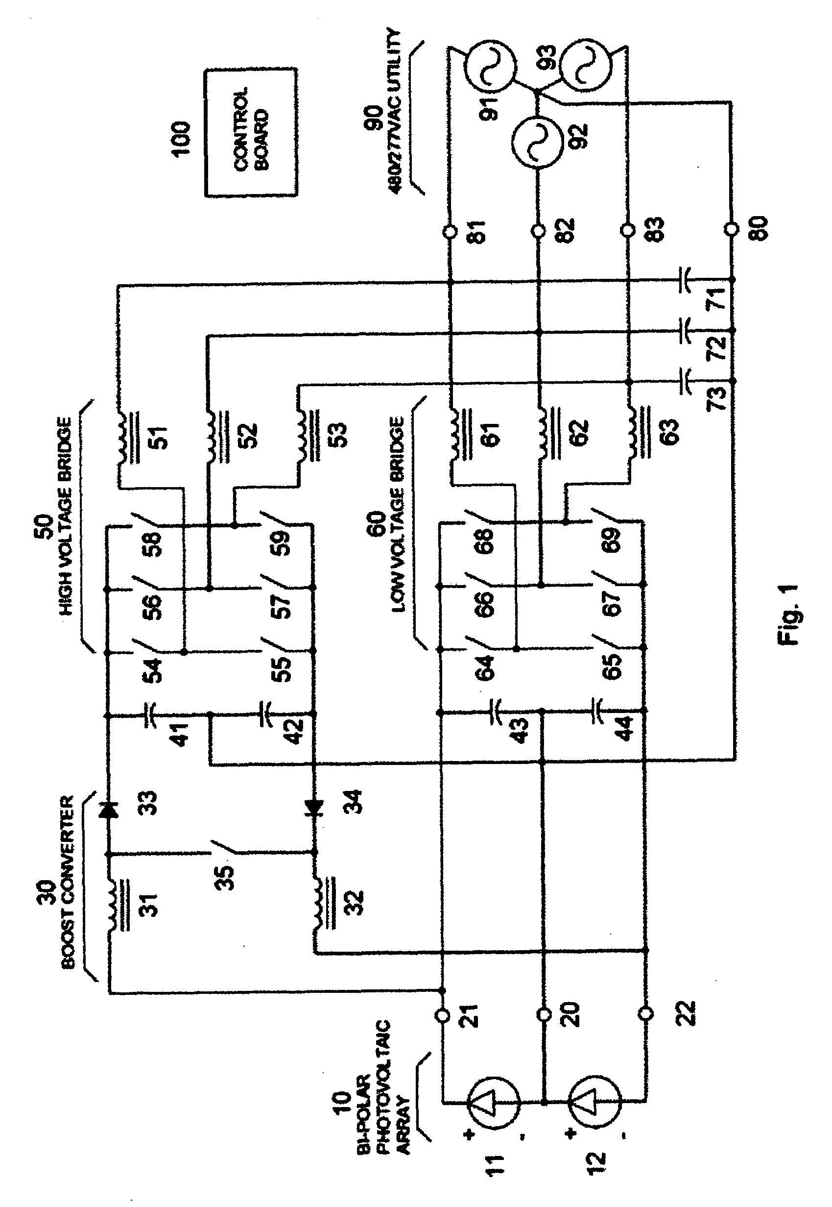
[0010]FIG. 1 illustrates the preferred embodiment of the invention. Photovoltaic arrays 11 and 12 are connected in a bipolar configuration at the input of the power converter. Terminal 21 is positive with respect to ground, terminal 22 is negative with respect to ground and terminal 20 is reference to ground. Capacitors 43 and 44 are electrically connected across photovoltaic arrays 11 and 12 to form a low impedance DC bus for semiconductor switching elements 64-69. Semiconductor switching elements 64-69 are typically insulated gate bipolar transistors (IGBTs) arranged in a conventional three phase bridge arrangement with filter inductors 61-63. Switching elements 64 and 65 are switched on and off to create a pulse-width-modulated (PWM) high frequency pulse train. The pulse train is filtered by inductor 61. The current through inductor 61 is regulated by a servo loop, resident on control board 100, where the actual current through inductor 61 is compared to a desired sinusoidal curr...


PUM


Abstract

An electrical DC-to-AC power conversion apparatus is disclosed that is primarily intended for use with solar photovoltaic sources in electric utility grid-interactive applications. The invention improves the conversion efficiency and lowers the cost of DC-to-AC inverters. The enabling technology is a novel inverter circuit topology, where the bulk of the throughput power, from DC source to AC utility, is processed only once. The inverter does not require an isolation transformer and can be connected directly to a 480 / 277 Vac utility grid. The invention also allows the power converter to start into photovoltaic array having higher open circuit voltages. The invention also uses active ripple current cancellation to substantially reduce the cost, size and weight of the main filter inductors.

Description

BACKGROUND OF THE INVENTION[0001]Photovoltaic (PV) cells produce power over a wide voltage range depending on the amount of sunlight and the temperature of the photovoltaic cell. There are National Electric Code and class-of-equipment restrictions that make PV arrays much more cost effective when sized for a maximum of 600 Vdc. In order to source AC power into the electric utility grid, over the expected range of DC voltages, prior art utility-interactive inverters use two power conversion stages.[0002]In all prior art topologies discussed, 100% of the throughput power is processed twice and power is lost in each conversion stage. The invention is an improvement over the prior art because the bulk of the DC-to-AC conversion is done in one direct conversion and only 0% to 25% of the throughput power is processes twice for a worst-case equivalent of 1¼ conversion steps, instead of 2. This translates to at least 38% less complexity, cost and conversion losses over the prior art.BRIEF D...

Claims


Application Information

Patent Timeline
Patent Type & Authority Applications(United States)
IPC IPC(8): G05F1/00
CPCH02M1/12Y02E10/56H02M2001/007H02M7/493Y10S323/906H02M7/501H02M1/007
Inventor WEST, RICK
Owner SCHNEIDER ELECTRIC SOLAR INVERTERS USA
Learn More