Pipeline lining method

a technology of pipe lining and pipe lining, which is applied in the direction of lamination, coating, chemistry apparatus and processes, etc., can solve the problems of reducing the amount of road space used at a construction site, reducing the amount of water consumed by the construction project, and improving the characteristics of the cured pipe lining material

Inactive Publication Date: 2007-11-29
SHONAN GOSEI JUSHI SEISAKUSHO KK
View PDF3 Cites 4 Cited by
  • Summary
  • Abstract
  • Description
  • Claims
  • Application Information

AI Technical Summary

Benefits of technology

[0012]In the present invention, the hot water or steam used to cure the thermosetting resin is pumped out to an external location and cooled to generate cooling water, which is then used to cool the cured pipe lining material. Therefore, a water truck for cooling need not be provided, the amount of road space used at a construction site is reduced, and the amount of water consumed by the construction project can be minimized. In addition, the high-temperature pipe lining material is cooled once the pipe lining material has been cured. Therefore, the characteristics of the cured pipe lining material can be improved.

Problems solved by technology

A problem therefore arises in that the water truck must be transported and a parking space must be made available for the water truck.
Other difficulties have been encountered in the conventional methods for curing the lining material.
With methods for filling the pipe with hot water, a large amount of water is required.
With methods in which the hot water is sprayed in a punctual pattern, the temperature of the entire lining material is not readily controlled.
Therefore, some parts of the lining material will become hot before other parts, curing will be inconsistent, and a stable quality will not be readily guaranteed.
Furthermore, dramatic variations occur due to pressure and hole size when hot water is sprayed, and uniform spraying is not readily achieved.

Method used


Image

  • Pipeline lining method
  • Pipeline lining method
  • Pipeline lining method

Examples


Embodiment Construction

[0027]The present invention will now be described in detail with reference to the embodiments shown in the accompanying drawings.

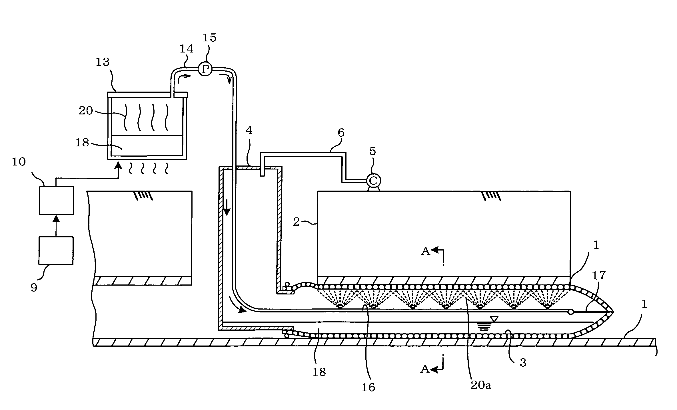
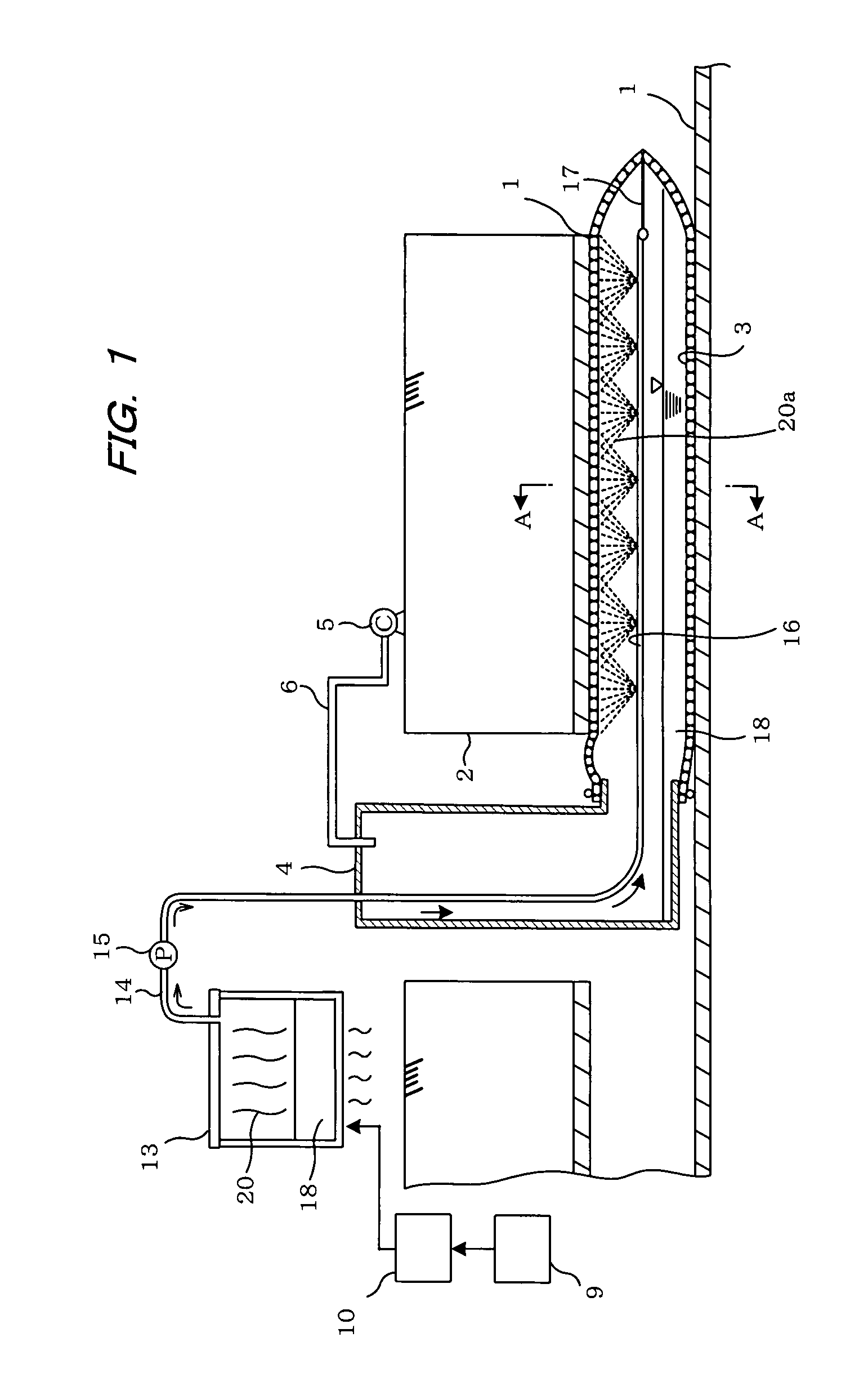
[0028]FIG. 1 is a cross-sectional view showing a pipeline lining method. The reference symbol 1 indicates a sewer pipe or another aging pipeline buried under ground. When the pipeline is repaired, a flexible tubular pipe lining material 3 is first set at the entry of the pipeline 1 from a manhole 2 that is in communication with the pipeline 1, and compressed air or another pressurized medium is enacted upon a pressure container 4 from an air compressor 5 via a pipe 6. This causes the pipe lining material 3 to be turned inside out and inserted into the pipeline 1.

[0029]The lining material 3 is made of a non-woven fabric composed of polyester, vinylon, acrylic, or another fiber that is sewn into a tubular shape to form a flexible tubular resin-absorbing material. The lining material 3 is impregnated with unsaturated polyester resin, vinyl ester resin, epoxy ...


PUM

PropertyMeasurementUnit
temperatureaaaaaaaaaa
air pressureaaaaaaaaaa

Abstract

A tubular pipe lining material impregnated with a thermosetting resin is inserted into a pipeline and made to expand and press against an inner peripheral surface thereof. Hot water or steam is sprayed onto the pipe lining material to cure the thermosetting resin impregnated therein. Hot water that has accumulated in a bottom part of the pipe lining material is pumped out to an external location by a pump and cooled by a cooling device to generate cool water, which is then sprayed via a hose onto the cured pipe lining material to thereby cool the heated pipe lining material. This enables the thermally cured pipeline lining material to be reliably cooled and rendering a water truck unnecessary that is required at a construction site to supply additional cooling water.

Description

BACKGROUND OF THE INVENTION[0001]1. Field of the Invention[0002]The present invention relates to a pipeline lining method, and more specifically relates to a pipeline lining method for lining a pipeline in order to repair an aged pipeline.[0003]2. Description of the Prior Art[0004]In order to repair an aged sewer pipe or other pipeline buried under ground without removing it therefrom, pipeline lining methods have been proposed in which a tubular pipe lining material impregnated with a thermosetting resin is inserted into the pipeline, the pipe lining material is expanded by air pressure or the like and pressed against an inner peripheral surface of the pipeline, and the thermosetting resin impregnated in the pipe lining material is heated and cured to line the pipeline. To heat and cure the pipe lining material, a method is employed in which steam (water vapor) or a hot water shower is used. A heating method is also proposed in which hot water is sprayed or made into a mist, or in ...

Claims


Application Information

Patent Timeline
Patent Type & Authority Applications(United States)
IPC IPC(8): B05D7/22
CPCB29C35/041B29C35/049B29C2035/1616B29C63/34B29C63/0069
Inventor KAMIYAMA, TAKAOKANETA, KOJIFUJII, KENJIMIURA, KATSUYORI
Owner SHONAN GOSEI JUSHI SEISAKUSHO KK
Why Eureka
Try Eureka