Diagnostic apparatus and method

a technology of diagnostic equipment and apparatus, applied in the direction of instruments, structural/machine measurement, vehicle testing, etc., can solve the problems of not being able to obtain the operation model of diagnostic objects, such as the operation model of apparatus, apparatus being developed, etc., and achieve the effect of convenient application

Inactive Publication Date: 2007-11-29
ENT SERVICES DEV CORP LP
View PDF4 Cites 5 Cited by
  • Summary
  • Abstract
  • Description
  • Claims
  • Application Information

AI Technical Summary

Benefits of technology

[0018] According to the diagnostic apparatus of the present invention and its method, it is possible to diagnose a diagnosis object without using any operation models.
[0019] The diagnostic apparatus of the present invention and its method can be easily applied to diagnosis / monitoring of objects having large individual differences, for example, diagnosis objects produced only by a very small number or diagnosis objects being developed.

Problems solved by technology

However, operation models of diagnostic objects, such as operation models of apparatus each to be produced only by one or a small number and an apparatus being developed, may not be obtained.

Method used


Image

  • Diagnostic apparatus and method
  • Diagnostic apparatus and method
  • Diagnostic apparatus and method

Examples


first embodiment

[0035] A first embodiment of the present invention will be described below.

[0036] [Operation Diagnostic System 1]

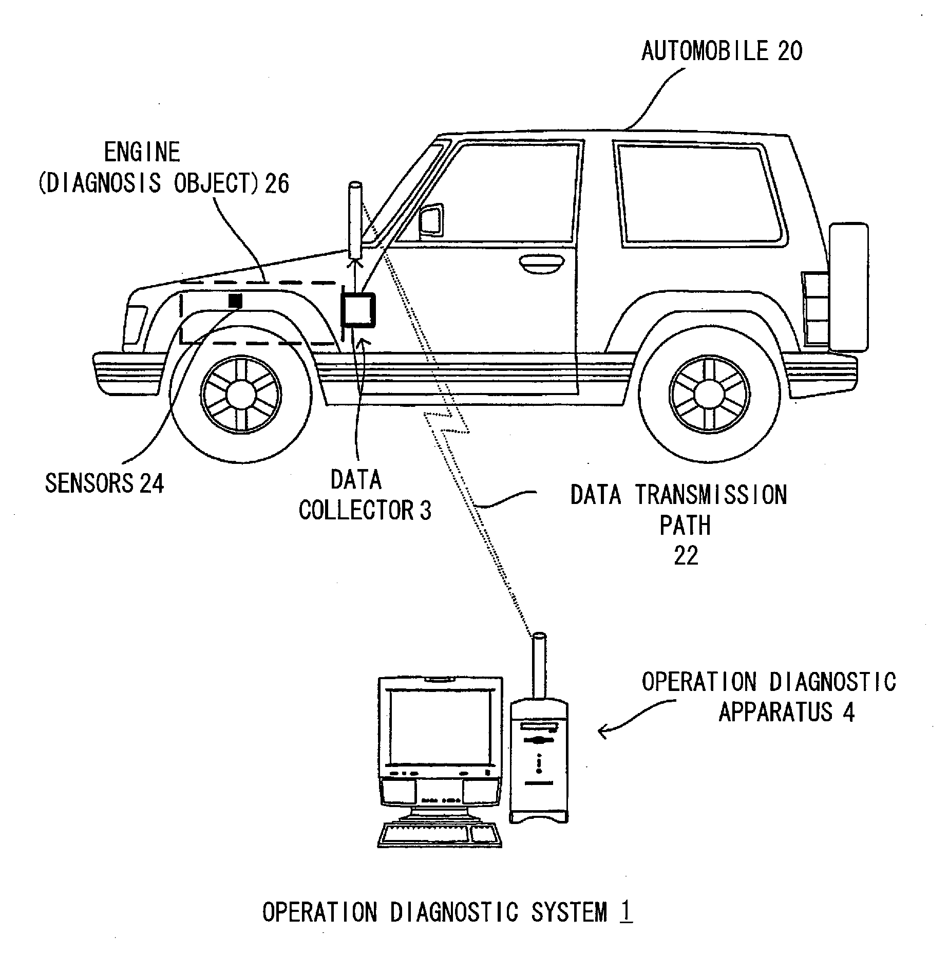
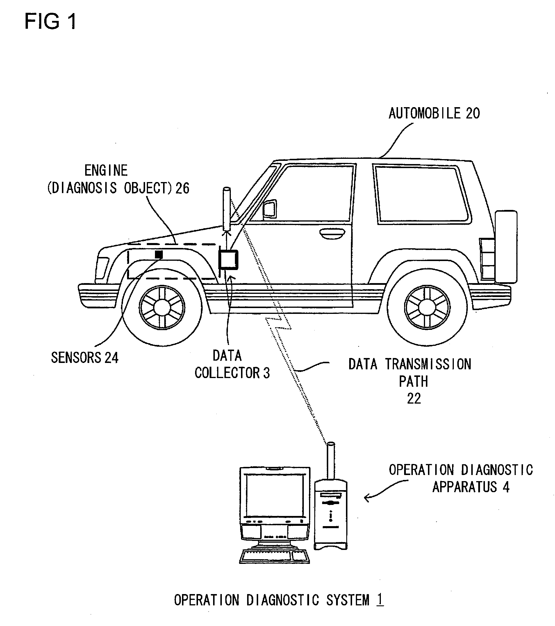
[0037]FIG. 1 is a diagram showing an operation diagnostic system 1 according to the present invention.

[0038] Substantially same components among components shown in the drawings will be denoted below by same reference numerals.

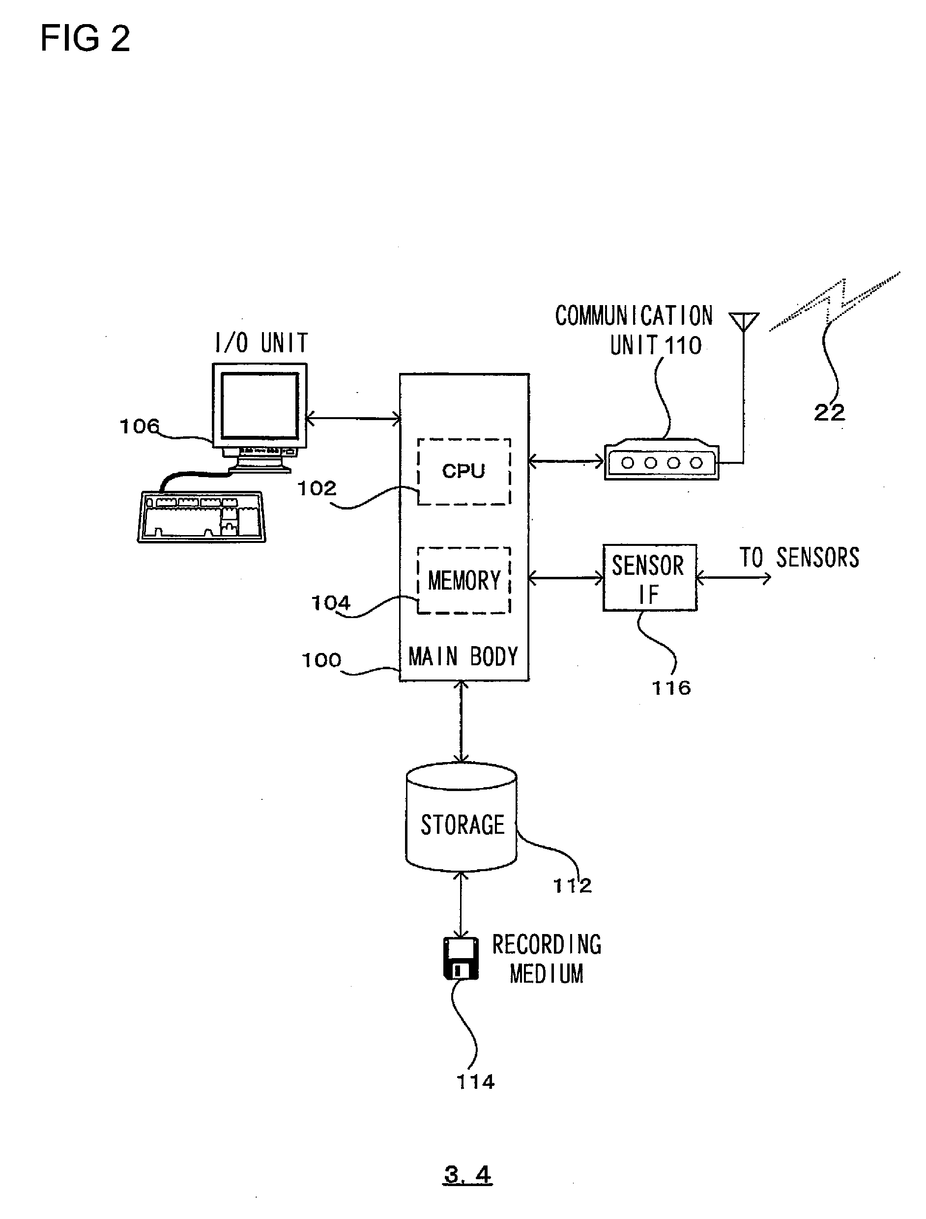
[0039] As shown in FIG. 1, an operation diagnostic system 1 includes a data collector 3 and an operation diagnostic apparatus 4 connected via a wire or wireless data transmission line 22.

[0040] The operation diagnostic system 1 can be applied to various transport machines by mounting a sensor to a component such as an engine of an aircraft or a ship in addition to an automobile. For clearer and more specific explanation, a case of applying the operation diagnostic system 1 to the automobile will be described below as a specific example.

[0041] The operation diagnostic system 1 can be applied to various purposes which need automatic operation dia...

second embodiment

[0147] A diagnostic apparatus capable of performing parallel operation diagnoses for the plurality of states shown in FIG. 5 or the like according to a second embodiment of the present invention will be described below.

[0148] To realize parallel diagnoses for the plurality of states, in the operation diagnostic apparatus 4 (FIGS. 1 and 2), a second operation diagnostic program 50 below is executed in place of the first operation diagnostic program 40 (FIG. 4).

[0149] [Operation Diagnostic Program 50]

[0150]FIG. 12 is a diagram showing a structure of the second operation diagnostic program 50 executed in place of the first operation diagnostic program 40 shown in FIG. 4 in the operation diagnostic apparatus 4 shown in FIGS. 1 and 2.

[0151] As shown in FIG. 12, for example, the operation diagnostic program 50 includes operation diagnostic sections 52-1 to 52-n which are disposed for each state to be subjected to operation diagnosis, such as the states of the engine 26 shown in FIG. 5 ...


PUM


Abstract

Provided is a diagnostic apparatus easily applied to diagnosis of a small lot product, etc. When measurement data on a measurement object is inputted sequentially, a filter section (408) performs filtering of the measurement data. When new measurement data is employed as diagnosis object data, a statistic processing section (420) updates diagnosis reference data using the new diagnosis object data. A diagnostic section (416) diagnoses the diagnosis object data based on the diagnosis reference data and determines whether an abnormality is present or not. If an abnormality is present, the fact is displayed to a user along with diagnosis results through an UI section (428).

Description

TECHNICAL FIELD [0001] The present invention relates to a diagnostic apparatus for diagnosing / monitoring an operation and a state change etc. of a measurement object based on a measurement value obtained from the measurement object, and its method. BACKGROUND ART [0002] For example, Patent Document 1 discloses a method of detecting a fault of a control system by using an operation model. [0003] However, operation models of diagnostic objects, such as operation models of apparatus each to be produced only by one or a small number and an apparatus being developed, may not be obtained. [0004] Accordingly, the method disclosed in Patent Document 1 cannot be applied to such the apparatus. [0005] [Patent Document 1] JP Publication of Unexamined Patent Application S57-041708 DISCLOSURE OF THE INVENTION Problems to be solved by the Invention [0006] The present invention has been made in view of the above-mentioned circumstances, and it is an object of the invention to provide a diagnostic a...

Claims


Application Information

Patent Timeline
Patent Type & Authority Applications(United States)
IPC IPC(8): G01D21/00G01D1/18G01M15/00G07C5/00
CPCG07C5/008G01D1/18
Inventor MISAWA, MASANORIISHIGAKI, SHINYA
Owner ENT SERVICES DEV CORP LP
Why Eureka
Try Eureka