
Marine vessel running controlling apparatus, and marine vessel employing the same

a controlling apparatus and marine technology, applied in the direction of process and machine control, electric devices, underwater equipment, etc., can solve the problems of reducing the automatic attitude control apparatus is no longer operative, and the stability of the marine vessel is steadily non-zero roll angle, etc., to reduce the resistance received by the marine vessel during the travel and reduce the propulsive efficiency of the propulsion system

Active Publication Date: 2007-11-29
YAMAHA MOTOR CO LTD
View PDF5 Cites 11 Cited by
  • Summary
  • Abstract
  • Description
  • Claims
  • Application Information

AI Technical Summary

Benefits of technology

The present invention provides a marine vessel running controlling apparatus that can automatically adjust the steering angle of the vessel based on the direction it is traveling, while also controlling the lift force difference between the port and starboard sides of the vessel to keep it consistent with the direction of travel. This allows for a reduction or nullification of the heel angle of the vessel, even when the steering angle is reduced or nullified during steering operations. This results in a more efficient and consistent operation of the marine vessel, reducing resistance and improving propulsive efficiency. Additionally, the apparatus can detect the turning state of the vessel and adjust the steering angle accordingly, further improving the control state and minimizing the turning of the vessel.

Problems solved by technology

On the other hand, the marine vessel steadily has a non-zero roll angle over a long period of time when traveling with its gravity center shifted to a starboard side or a port side due to unevenly loaded cargo or due to wind blowing on its broadside.
This reduces the propulsive efficiency of a propulsion system 83.
If the operator performs a steering operation to nullify the heel angle, however, the automatic attitude controlling apparatus is no longer operative.
Therefore, the marine vessel continuously travels with its propulsion system driven at a reduced propulsive efficiency.

Method used


Image

  • Marine vessel running controlling apparatus, and marine vessel employing the same
  • Marine vessel running controlling apparatus, and marine vessel employing the same
  • Marine vessel running controlling apparatus, and marine vessel employing the same

Examples


Embodiment Construction

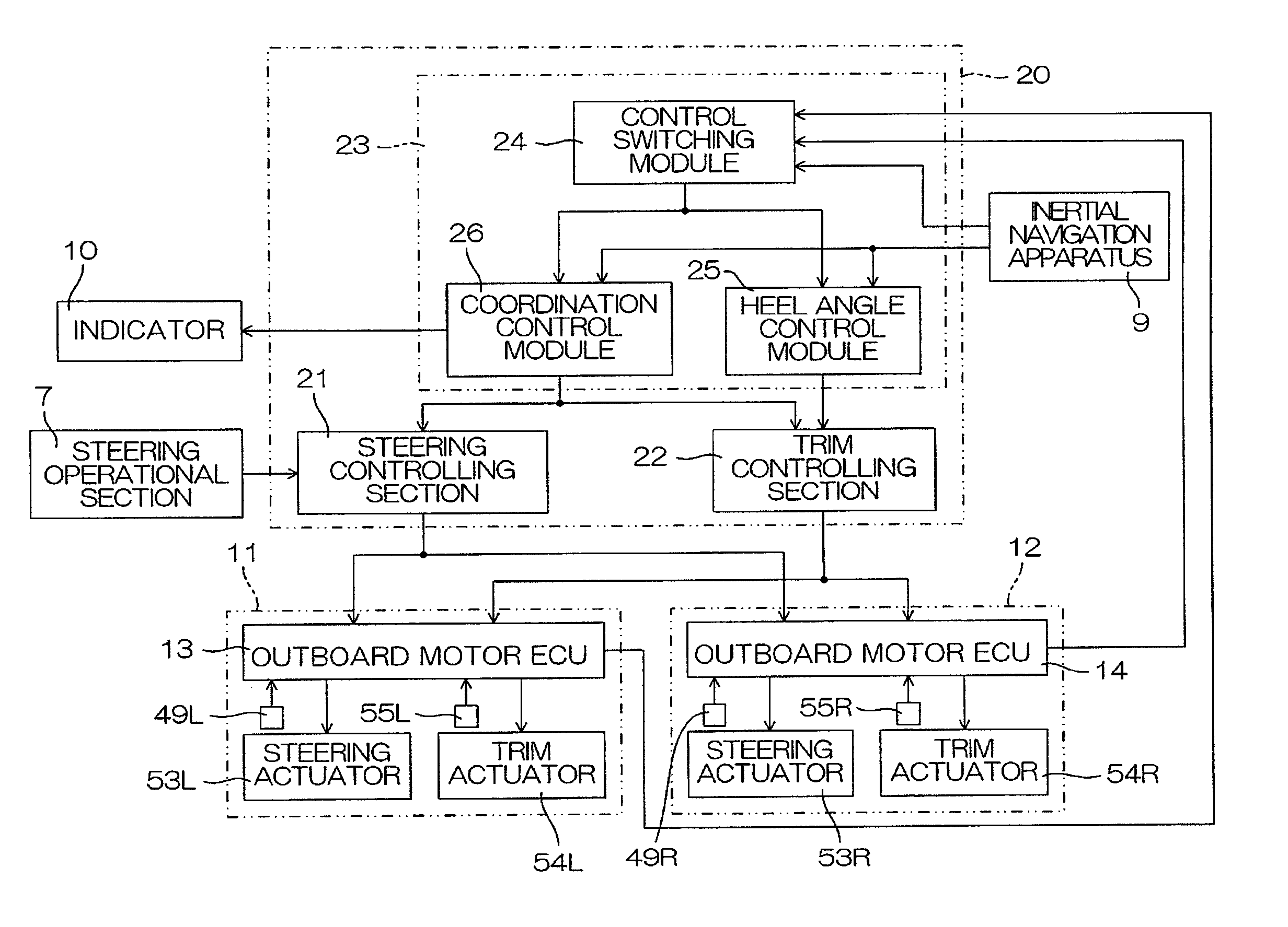
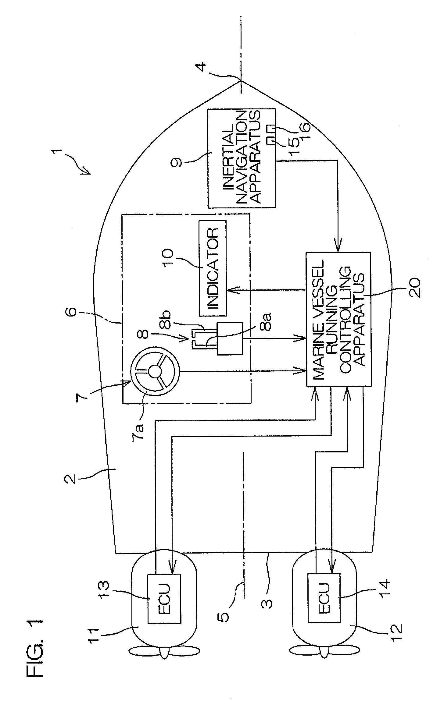
[0041]FIG. 1 is a schematic diagram for explaining the construction of a marine vessel 1 according to a first preferred embodiment of the present invention. The marine vessel 1 is preferably a relatively small-scale marine vessel, such as a cruiser or a boat, and includes a pair of outboard motors 11, 12 attached to a stern (transom) 3 of a hull 2, for example. The outboard motors 11, 12 are positioned laterally symmetrically with respect to a center line 5 of the hull 2 extending through the stern 3 and a bow 4 of the hull 2. That is, the outboard motor 11 is attached to a rear port-side portion of the hull 2, while the outboard motor 12 is attached to a rear starboard-side portion of the hull 2. The outboard motor 11 and the outboard motor 12 may hereinafter be referred to as “port-side outboard motor 11” and “starboard-side outboard motor 12”, respectively, for differentiation therebetween. Electronic control units 13 and 14 (hereinafter referred to as “outboard motor ECU 13” and...


PUM


Abstract

A marine vessel running controlling apparatus includes a steering angle acquiring unit which acquires the steering angle of a steering mechanism provided in a marine vessel, and a control unit which controls a lift force difference generating unit for generating a lift force difference between a port side and a starboard side of the marine vessel according to the steering angle acquired by the steering angle acquiring unit. The control unit may control the lift force difference generating unit to increase the heel angle of the marine vessel in a direction defined by the steering angle, if the steering angle falls outside a neutral range.

Description

BACKGROUND OF THE INVENTION [0001] 1. Field of the Invention [0002] The present invention relates to a marine vessel including a lift force difference generating unit which generates a lift force difference between a port side and a starboard side of the marine vessel, and a marine vessel running controlling apparatus for a marine vessel. [0003] 2. Description of the Related Art [0004] An inertial navigation system provided in a marine vessel is generally capable of detecting the yaw angular speed, the roll angle, and the pitch angle of the marine vessel. In an ordinary marine vessel running state, the roll angle of the marine vessel is zero during straight traveling of the marine vessel, and is non-zero during turning of the marine vessel. On the other hand, the marine vessel steadily has a non-zero roll angle over a long period of time when traveling with its gravity center shifted to a starboard side or a port side due to unevenly loaded cargo or due to wind blowing on its broads...

Claims


Application Information

Patent Timeline
Patent Type & Authority Applications(United States)
IPC IPC(8): B62D6/00
CPCB63B39/061B63H20/10B63H2020/003B63H25/02B63H20/12
Inventor KAJI, HIROTAKA
Owner YAMAHA MOTOR CO LTD
Learn More