
Causal ladder mechanism for proactive problem determination, avoidance and recovery

a ladder mechanism and problem solving technology, applied in the direction of nuclear elements, instruments, wireless commuication services, etc., can solve the problems of complex system, shortage of skilled it workers to manage, and complex system today, and achieve the effect of proactive problem determination

Active Publication Date: 2007-11-29
TREND MICRO INC
View PDF13 Cites 35 Cited by
  • Summary
  • Abstract
  • Description
  • Claims
  • Application Information

AI Technical Summary

Benefits of technology

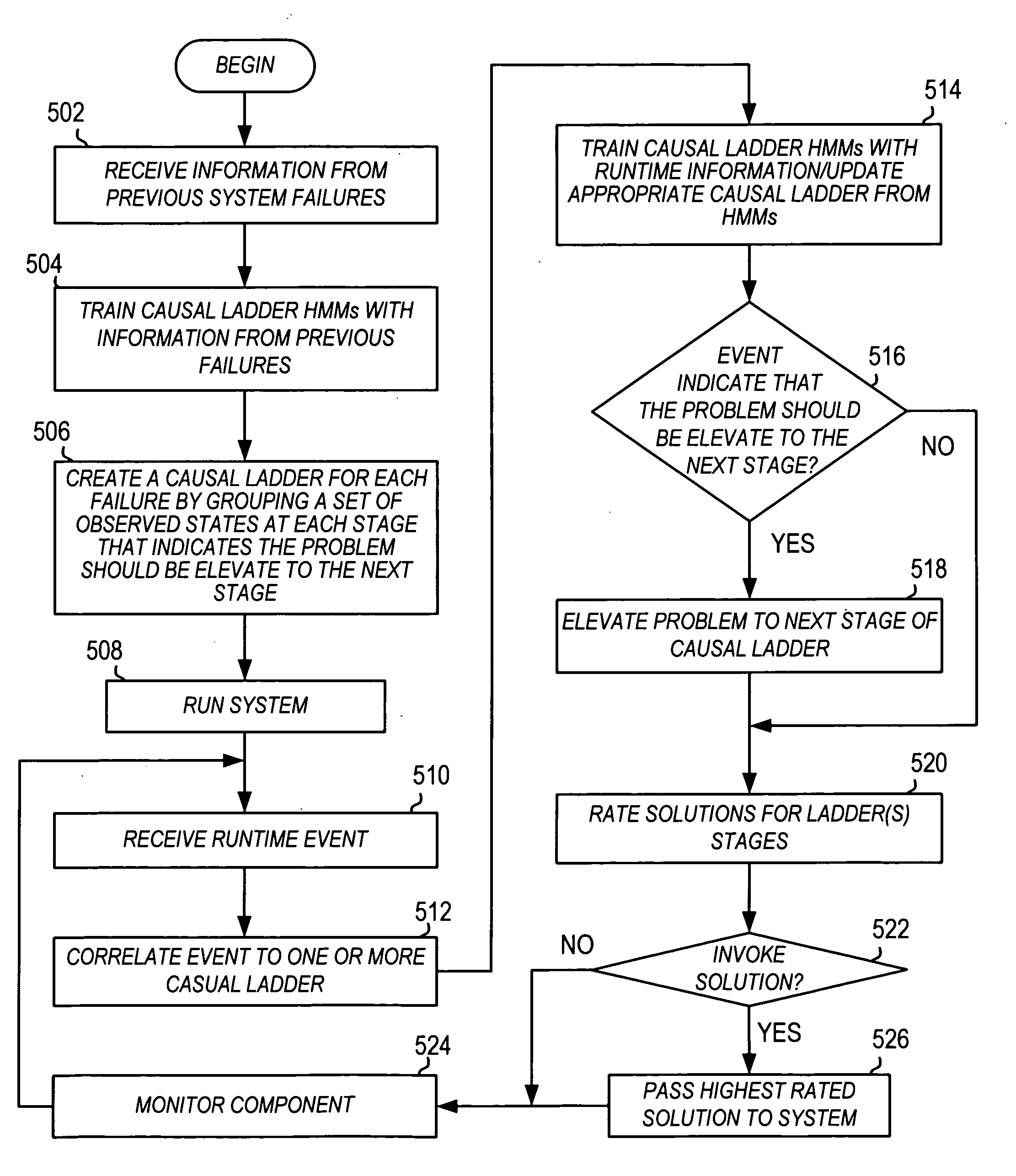
[0014]FIG. 5 is a flowchart depicting a method for proactive problem determination avoidance and recovery using a causal ladder mechanism in accordance with an exemplary embodiment of the present invention.

Problems solved by technology

This boom has also led to some complexity in the systems.
Systems today are highly complex comprising of numerous components (servers, virtual machines, CPUs) from different vendors operating in a geographically distributed environment.
Additionally, the complexity of these systems and the way they work together has and will create a shortage of skilled IT workers to manage all of the systems.
The problem is expected to increase exponentially, just as the dependence on technology has.
As access to information becomes omnipresent through PC's, hand-held and wireless devices, the stability of current infrastructure, systems, and data is at an increasingly greater risk to suffer outages and general disrepair
However, most problem determination and mitigation solutions today assume that the system is entirely deterministic and hence use automation to fix problems based on rules developed at design time.
Traditionally, problems in complex systems are reactive in nature, typically by gathering and then inspecting log and / or trace files.
However, these log / trace files do not have a way to capture any particular variations of a components behavior.

Method used


Image

  • Causal ladder mechanism for proactive problem determination, avoidance and recovery
  • Causal ladder mechanism for proactive problem determination, avoidance and recovery
  • Causal ladder mechanism for proactive problem determination, avoidance and recovery

Examples


Embodiment Construction

[0016]As will be appreciated by one of skill in the art, the present invention may be embodied as a method, system, or computer program product. Accordingly, the present invention may take the form of an entirely hardware embodiment, an entirely software embodiment (including firmware, resident software, micro-code, etc.) or an embodiment combining software and hardware aspects all generally referred to herein as a “circuit” or “module.” Furthermore, the present invention may take the form of a computer program product on a computer-usable storage medium having computer-usable program code embodied in the medium.

[0017]Any suitable computer readable medium may be utilized. The computer-usable or computer-readable medium may be, for example but not limited to, an electronic, magnetic, optical, electromagnetic, infrared, or semiconductor system, apparatus, device, or propagation medium. More specific examples (a nonexhaustive list) of the computer-readable medium would include the foll...


PUM


Abstract

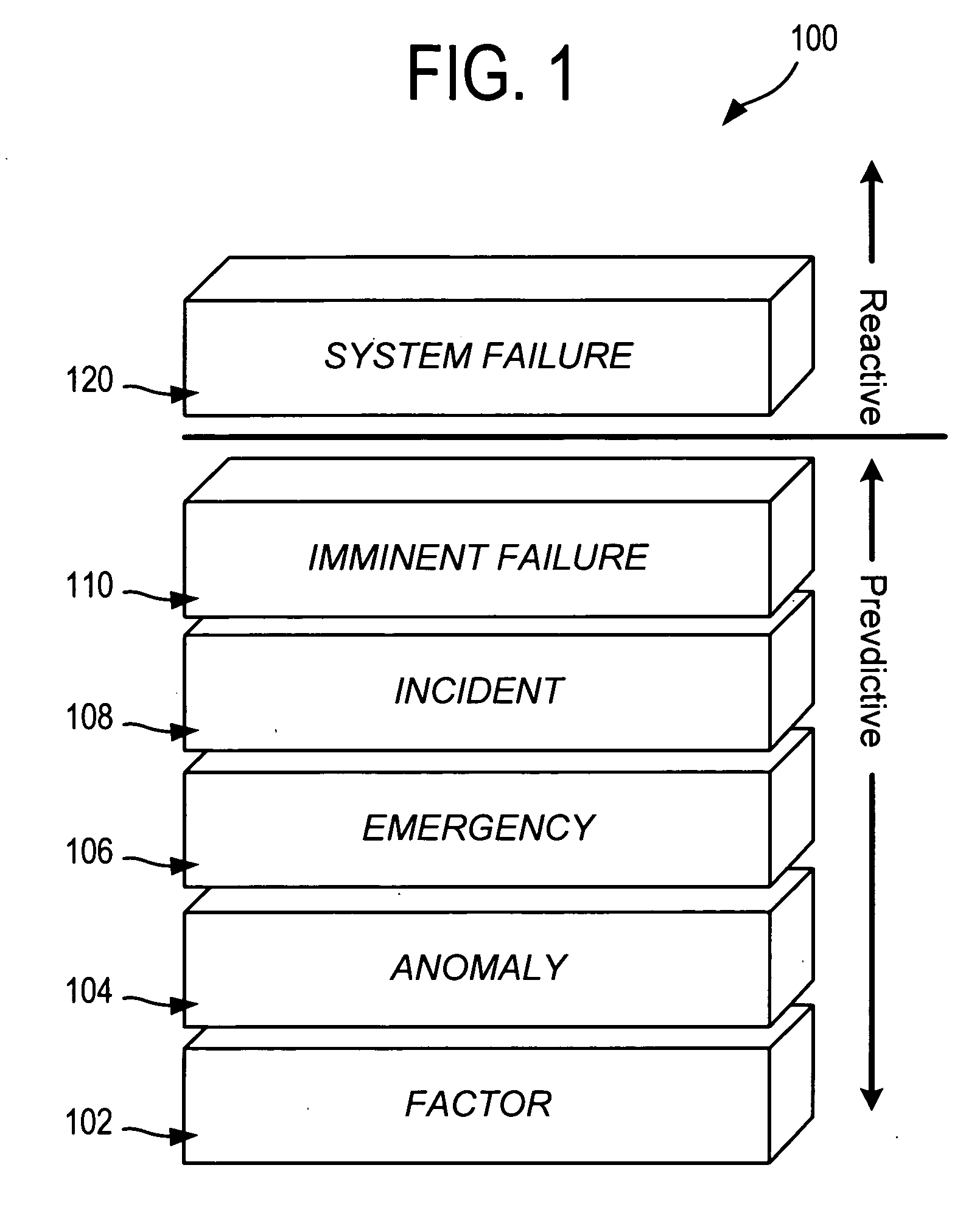
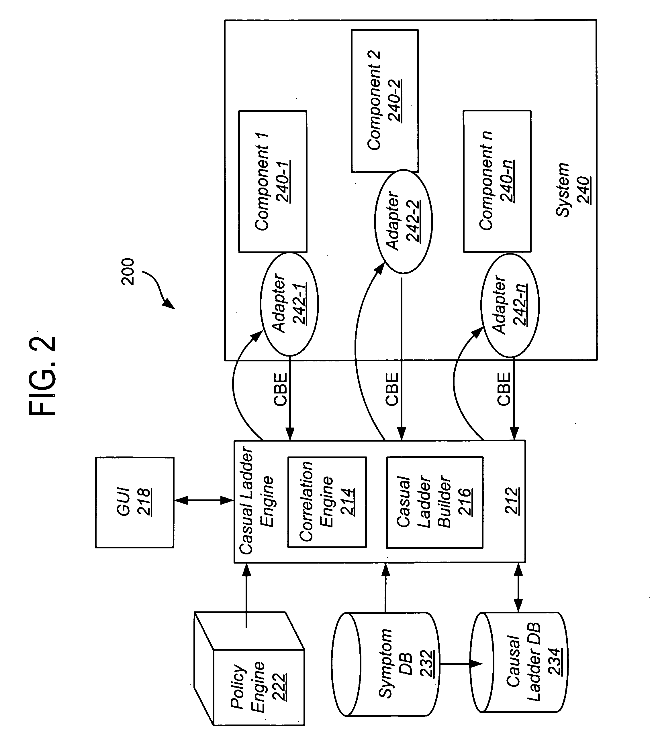
A plurality of causal ladder is assembled in advance from component system events taken from previous system failures. The ladders classify the various transitions the system goes through from one set of observed states to another in multiple stages representing issues of differing urgency, importance and need for remediation. These stages are used at runtime to determine the criticality of any abnormal system activity and to accurately predict the component failure prior to the system crashing. Each ladder comprises a plurality of elevated stages representing criticality of the problem. At runtime, the causal ladder engine correlates real-time events received from the system to stages of one or more pre-constructed causal ladders and identifies a probable problem (and / or the faulty component) from the corresponding causal ladder. The causal ladder engine also determines the stage of the problem from event occurrences. At each stage, a different potential solution is identified for the problem.

Description

BACKGROUND OF THE INVENTION[0001]The present invention relates representing a worsening system state transition as a causal sequence and using the causal sequence at runtime for problem determination avoidance and recovery from problems in complex systems.[0002]Within the past two decades the development of raw computing power coupled with the proliferation of computer devices has grown at exponential rates. This growth along with the advent of the Internet has led to a new age of accessibility—to other people, other systems, and to information. This boom has also led to some complexity in the systems. The simultaneous explosion of information and integration of technology into everyday life has brought on new demands for how people manage and maintain computer systems.[0003]Systems today are highly complex comprising of numerous components (servers, virtual machines, CPUs) from different vendors operating in a geographically distributed environment. A clustered Enterprise Applicati...

Claims


Application Information

Patent Timeline
Patent Type & Authority Applications(United States)
IPC IPC(8): G06F11/34G06F19/00G06F17/40G06F11/30
CPCG06F11/008
Inventor SUBRAMANIAN, BALANCHALASANI, NANCHARIAH RAGHUVEERARAHMAN, JAVEDWESLEY, AJAMU A.
Owner TREND MICRO INC
Learn More