Brake system

Active Publication Date: 2007-12-06
HONDA MOTOR CO LTD
View PDF8 Cites 54 Cited by
  • Summary
  • Abstract
  • Description
  • Claims
  • Application Information

AI Technical Summary

Benefits of technology

[0022] With this arrangement, the piston of the electrical fluid pressure generation device advances to the position beyond the first port to provide communication between the first port and the second port before the master cylinder generates the brake fluid pressure. Therefore, it is possible to

Problems solved by technology

Therefore, the wheel cylinders can be operated by the brake fluid pressure generated by the electrical fluid pressure generation device in a normal situation where the electrical fluid pressure generatio

Method used


Image

  • Brake system
  • Brake system
  • Brake system

Examples


Example

[0033] A first embodiment of the present invention will be described with reference to FIGS. 1 and 2.

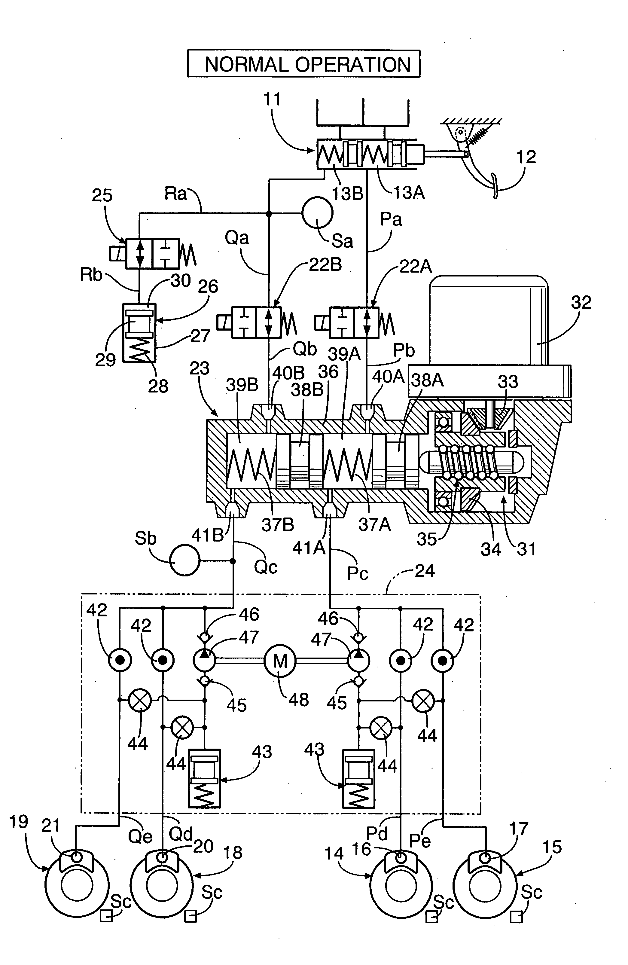
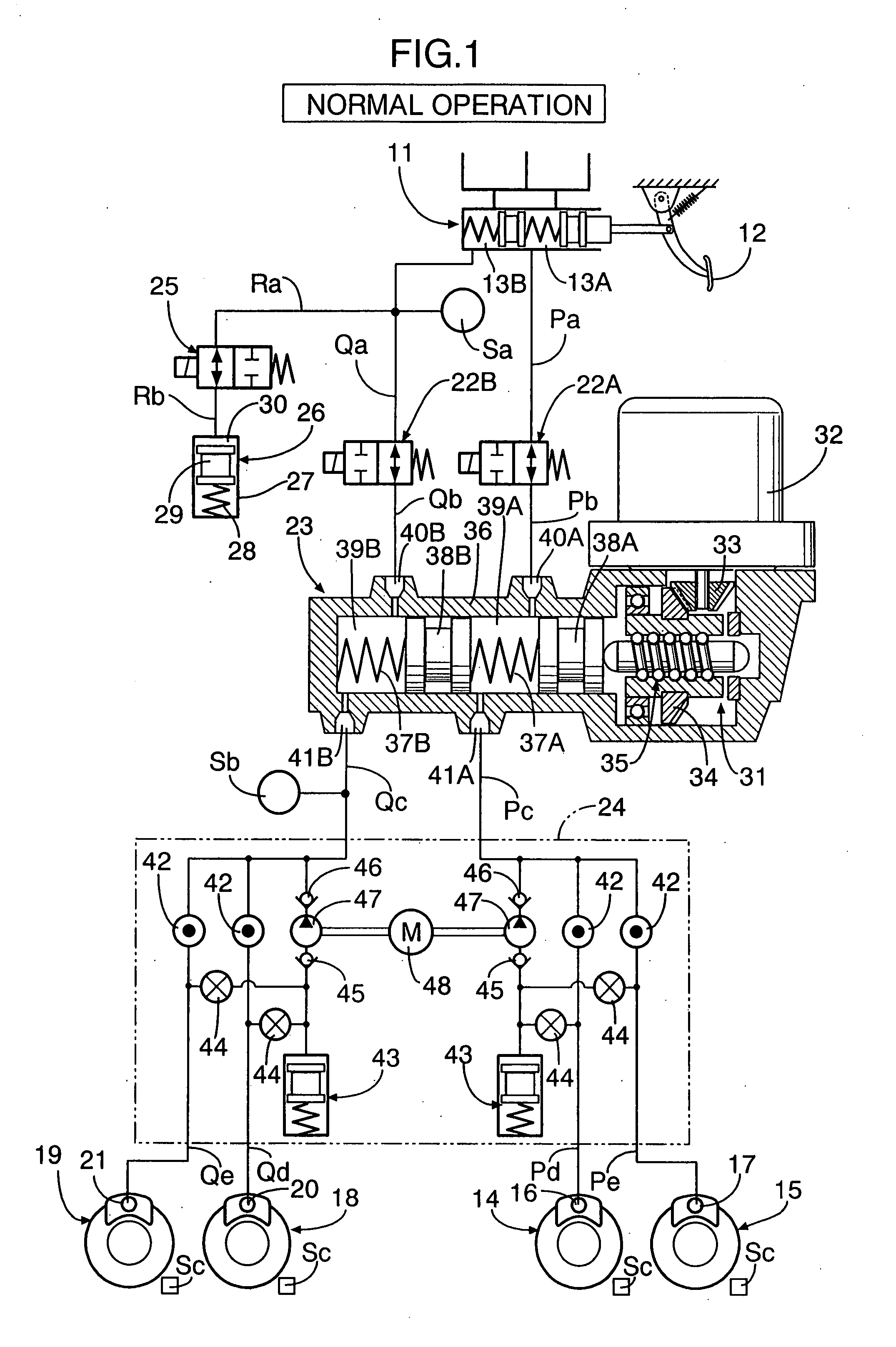
[0034] As shown in FIG. 1, a tandem master cylinder 11 has two first fluid pressure chambers 13A and 13B which output brake fluid pressure according to a force applied to a brake pedal 12 by a driver treading on the brake pedal 12. One of the first fluid pressure chambers 13A is connected to wheel cylinders 16 and 17 of disc brake devices 14 and 15 for braking, for example, a left front wheel and a right rear wheel through fluid passages Pa, Pb, Pc, Pd, and Pe. The other first fluid pressure chamber 13B is connected to wheel cylinders 20 and 21 of disc brake devices 18 and 19 for braking, for example, a right front wheel and a left rear wheel through fluid passages Qa, Qb, Qc, Qd, and Qe.

[0035] A shutoff valve 22A, which is a normally open solenoid valve, is provided between the fluid passages Pa and Pb. A shutoff valve 22B, which is a normally open solenoid valve, is provided betw...

Example

[0056] A second embodiment of the present invention will be described with reference to FIGS. 3 to 6.

[0057] In the first embodiment, the stroke simulator 26 is connected to the master cylinder 11 via the reaction force permission valve 25, but in the second embodiment the reaction force permission valve 25 is eliminated and the stroke simulator 26 is connected to the motor cylinder 23′. The second embodiment will be described focusing on differences between the second embodiment and the first embodiment. The components of the second embodiment corresponding to those of the first embodiment are denoted by the same reference numerals and symbols, and the overlapping description is omitted.

[0058] As is apparent from FIGS. 3 and 5, a rear fluid chamber 39A of a motor cylinder 23′ communicates with fluid passages Pb and Pc through a rear inlet port 40A and a rear outlet port 41A, and a front fluid chamber 39B communicates with fluid passages Qb and Qc through a front inlet port 40B and...


PUM


Abstract

In a brake system, two first fluid pressure chambers of a master cylinder respectively communicate with two second fluid pressure chambers of a motor cylinder. The two second chambers communicate with four wheel cylinders through an ABS. The wheel cylinders are operated by brake fluid pressure generated by the master cylinder in an abnormal situation where the motor cylinder is non-operational. The brake system includes two separate independent fluid pressure lines: one line extending from one of the first chambers in the master cylinder to the wheel cylinders via one of the second chambers in the motor cylinder; and the other line extending from the other first chamber in the master cylinder to the wheel cylinders via the other second chamber in the motor cylinder. Thus, even if an abnormality occurs in one of the two fluid pressure lines, a minimum necessary braking force is secured.

Description

CROSS-REFERENCE TO RELATED APPLICATIONS [0001] The present invention claims priority under 35 USC 119 based on Japanese patent application No. 2006-157460, filed on June 6, 2006, and Japanese patent application No. 2006-285647, filed on Oct. 20, 2006. The entirety of the subject matter of each of these priority documents is incorporated by reference herein. BACKGROUND OF THE INVENTION [0002] 1. Field of the Invention [0003] The present invention relates to a brake system having a master cylinder for generating brake fluid pressure based on a brake operation of a driver, and an electrical fluid pressure generation device for generating brake fluid pressure by an electrically controllable actuator. [0004] 2. Description of the Related Art [0005] Japanese Patent Application Laid-open No. 2003-137084 discloses a brake system of the type referred to as a brake by wire (BBW) brake system, which converts a brake operation of a driver into an electrical signal used to operate electrical flu...

Claims


Application Information

Patent Timeline
IPC IPC(8): B60T8/40
CPCB60T8/4081
Inventor HATANO, KUNIMICHI
Owner HONDA MOTOR CO LTD
Why Eureka
Try Eureka