Double resonance coil arrangement for a magnetic resonance device

a magnetic resonance device and double resonance coil technology, applied in the direction of magnetic measurement, measurement device, instruments, etc., can solve the problem that the conductive connection can only be realized with difficulty, and achieve the effect of improving the symmetry of the circuitry, improving the accuracy of the second capacitor, and facilitating matching

Inactive Publication Date: 2007-12-06
SIEMENS HEALTHCARE GMBH
View PDF7 Cites 16 Cited by
  • Summary
  • Abstract
  • Description
  • Claims
  • Application Information

AI Technical Summary

Benefits of technology

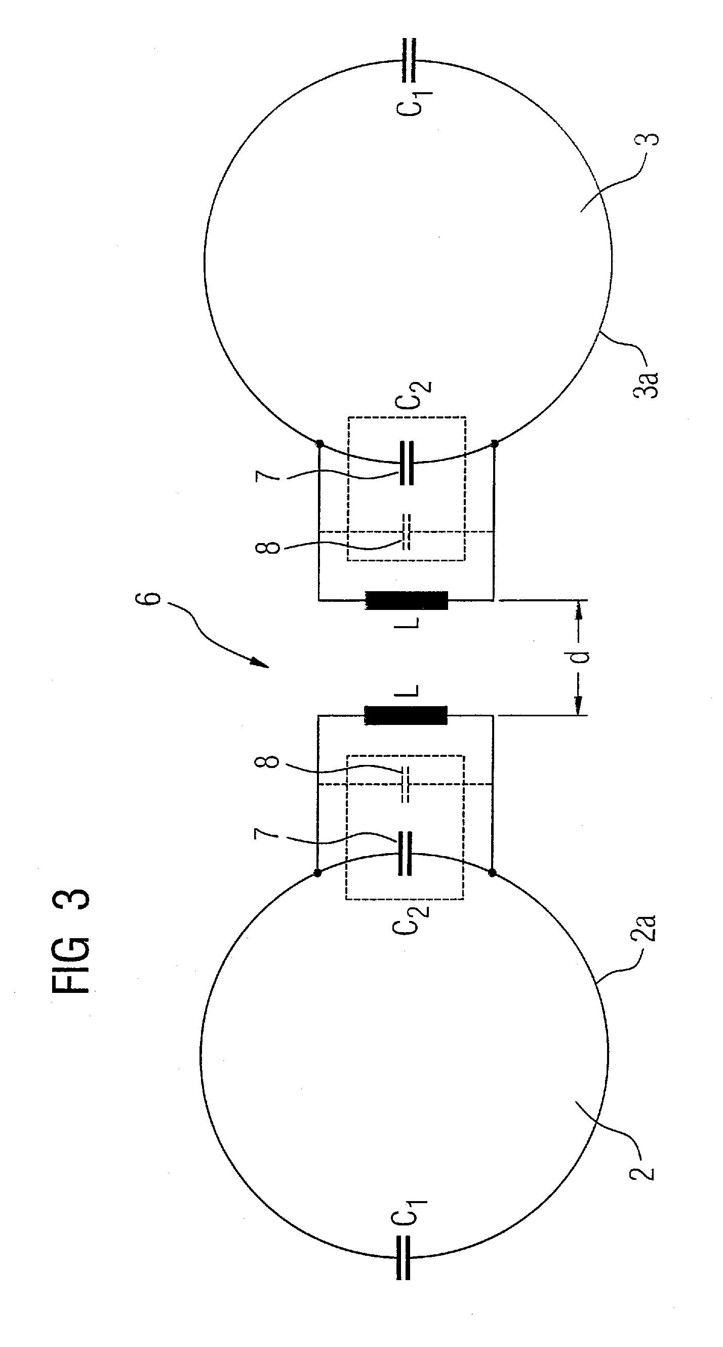
[0014] It is also possible for the second capacitor to be formed by the self-capacitance of the inductor and at least one discrete capacitor that is connected in parallel with the inductor. An additional component is still interconnected here in order to further adjust the second capacitor, this enabling a more precise dimensioning of the second capacitor.
[0015] To achieve an improved symmetry of the circuitry as well in the case of symmetrical arrangements and thus to enable an easier matching, the first capacitor and / or the second capacitor can be dimensioned identically in each instance.

Problems solved by technology

Head coil arrangements generally are formed by at least two housing parts that are separated from one another, between which conductive connections can only be realized with difficulty.

Method used


Image

  • Double resonance coil arrangement for a magnetic resonance device
  • Double resonance coil arrangement for a magnetic resonance device
  • Double resonance coil arrangement for a magnetic resonance device

Examples


Embodiment Construction

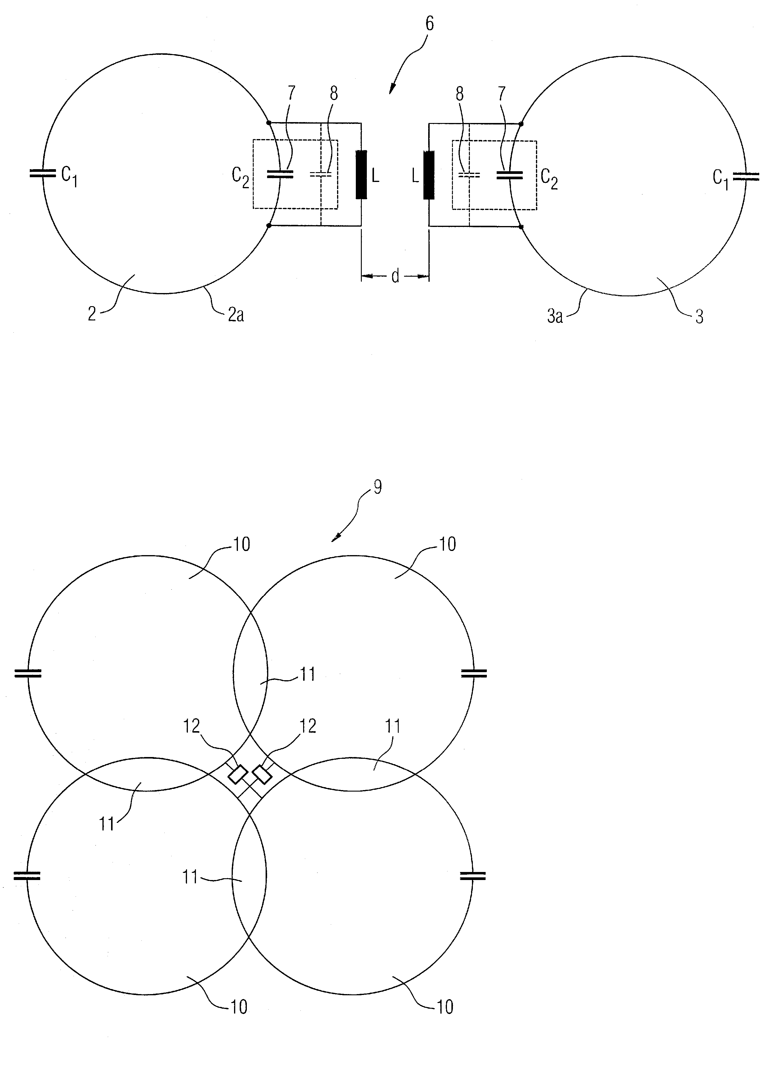
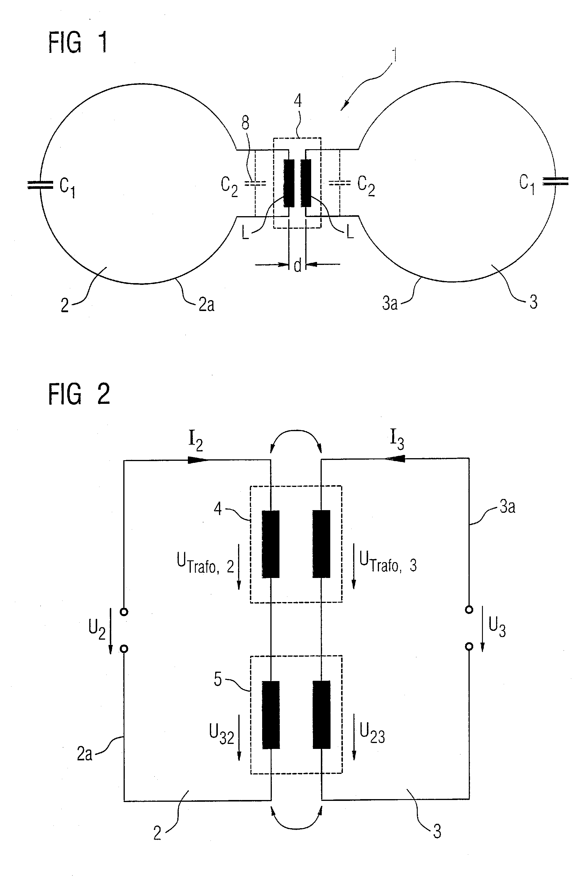
[0024]FIG. 1 shows the schematic diagram of a double resonance coil arrangement 1, which here has two coils 2 and 3. A first capacitor is C1 is connected in each instance in each of the coil conductors 2a, 3a. In addition, an inductor L is also connected in each instance in the coil conductors 2a and 3a. The two inductors L together form a transformer 4. They are distanced here by a distance d. The coils 2 and 3 are decoupled from one another by the transformer 4.

[0025] Each of the inductors L additionally embodies a self-capacitance 8, which is indicated here with a dashed line. This forms the second capacitor C2, which, together with the inductor L, forms an oscillating circuit.

[0026] The capacitors C1, C2, the inductor L and the distance d are dimensioned here such that each coil 2, 3 with the same frequencies is double resonant and the coils 2, 3 are decoupled among themselves by the transformer 4.

[0027] The principle of the decoupling arrangement by way of a trans-former can...


PUM


Abstract

A double resonance coil arrangement for a magnetic resonance device has at least two coils, each having a coil conductor, in which at least one first capacitor, as well as at least one inductor forming an oscillating circuit with a second capacitor, are connected. The inductors of two adjacently arranged coils are at a distance from one another and form a transformer. The capacitors, the inductor and the distance are dimensioned such that each coil is double resonant and the at least two coils are decoupled from each other by the transformer.

Description

BACKGROUND OF THE INVENTION [0001] 1. Field of the Invention [0002] The present invention relates to a double resonance coil arrangement for a magnetic resonance device of the type having at least two coils, each formed by a coil conductor in which at least one capacitor as well as at least one inductor forming an oscillating circuit with a further second capacitor are connected. [0003] 2. Description of the Prior Art [0004] If, for magnetic resonance data acquisition, nuclei other than hydrogen are to be excited and their signals received, for the purpose of spectroscopy or imaging for instance, it is advantageous to employ a detection coil arrangement that is sensitive both to hydrogen nuclei as well as to other types of nuclei (called X-nuclei below). It is then possible for instance to firstly re-cord a hydrogen overview image for localization purposes and then to execute X-nuclei spectroscopy or X-nuclei image data acquisition for instance. Such coil arrangements with two discr...

Claims


Application Information

Patent Timeline
Patent Type & Authority Applications(United States)
IPC IPC(8): G01V3/00
CPCG01R33/3415G01R33/365G01R33/3635
Inventor GREIM, HELMUTMATSCHI, VOLKER
Owner SIEMENS HEALTHCARE GMBH
Why Eureka
Try Eureka