Organic electroluminescence display and driving method thereof

a technology of electroluminescence display and organic electroluminescence, which is applied in the direction of electric digital data processing, instruments, computing, etc., can solve the problem of not being suitable for a large screen

Active Publication Date: 2007-12-06
SAMSUNG DISPLAY CO LTD
View PDF15 Cites 17 Cited by
  • Summary
  • Abstract
  • Description
  • Claims
  • Application Information

AI Technical Summary

Benefits of technology

[0022]According to an aspect of the present invention, a pixel of an electroluminescence device includes: a scan line to receive a scan signal; a data line to receive a data signal; and a transistor to control flow of current according to the data signal containing a data driving voltage component of different voltage levels to express brightness.

Problems solved by technology

As described above, the pixel as shown in FIG. 1 should include a circuit for compensating for an uneven threshold voltage, while the pixel as shown in FIG. 2 is not suitable for a large screen of the organic electroluminescence display since time needed for charging by a current is increased due to a parasitic capacitor, etc., and since the driving circuit is more complicated.

Method used


Image

  • Organic electroluminescence display and driving method thereof
  • Organic electroluminescence display and driving method thereof
  • Organic electroluminescence display and driving method thereof

Examples


Embodiment Construction

[0035]Reference will now be made in detail to aspects of the present invention, examples of which are illustrated in the accompanying drawings, wherein like reference numerals refer to the like elements throughout. The aspects are described below in order to explain the aspects by referring to the figures.

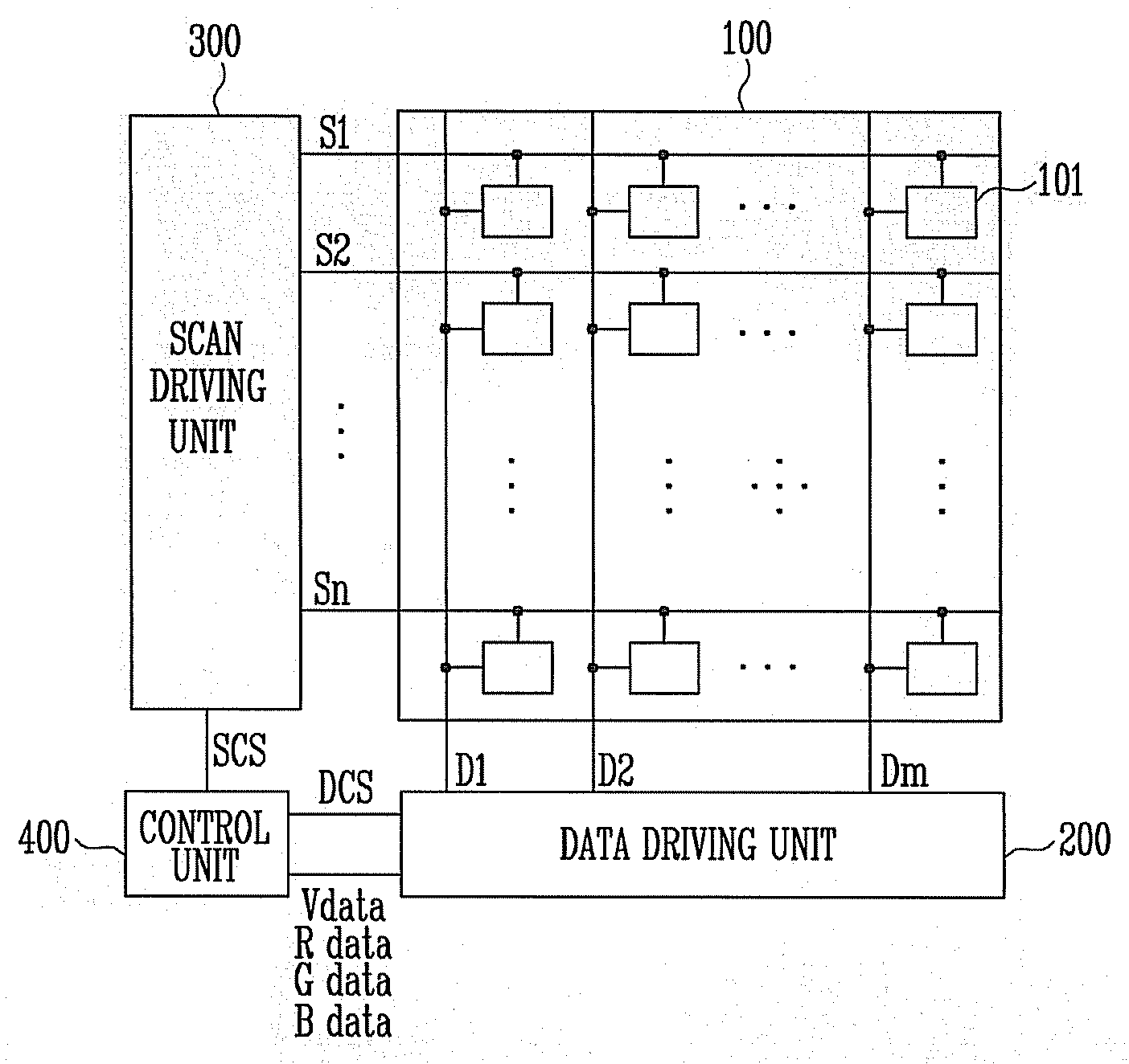
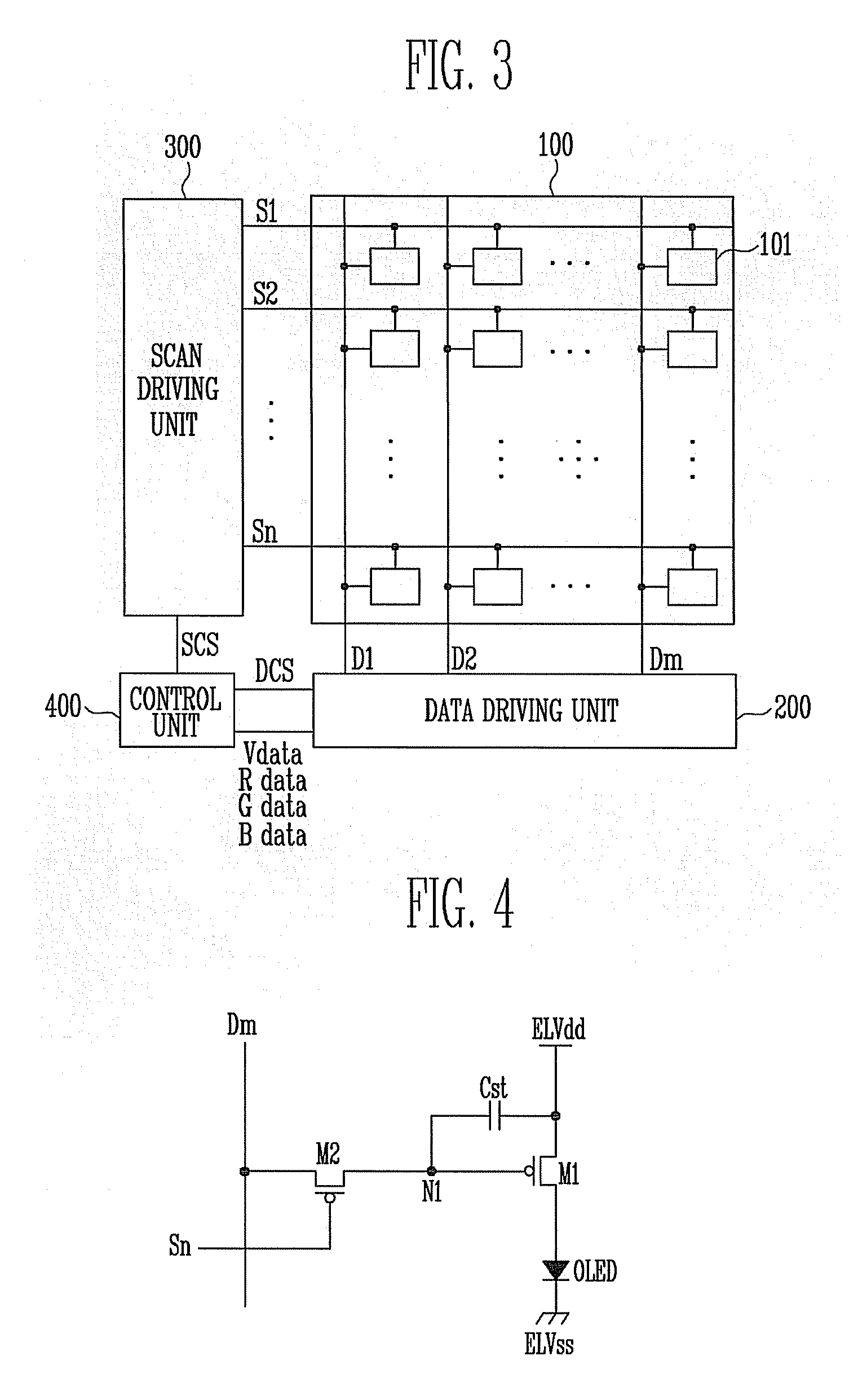
[0036]FIG. 3 is a schematic view showing a configuration of an organic electroluminescence display according to an aspect of the present invention. Referring to FIG. 3, the organic electroluminescence display includes a pixel unit 100, a data driving unit 200, a scan driving unit 300, and a control unit 400.

[0037]As shown, the pixel unit 100 includes a plurality of data lines (D1,D2 . . . Dm−1,Dm) and a plurality of scan lines (S1,S2 . . . Sn−1,Sn). A plurality of pixels are formed in a region defined by the plurality of data lines (D1,D2 . . . Dm−1,Dm) and the plurality of scan lines (S1,S2 . . . Sn−1,Sn). As shown, the pixel 101 includes a pixel circuit and an organic electrolumi...


PUM


Abstract

An organic electroluminescence display transmits a data driving voltage to a data driving unit to make different a voltage of the data signal outputted from the data driving unit, the data driving voltage being in a different level in every subframe according to the digital data signal, and displaying a desired grey level of an image by allowing a desired subframe to emit light according to the number of bits of the data signal, and a driving method thereof. An organic electroluminescence display includes a plurality of scan lines to transmit a scan signal; a plurality of data lines to transmit a digital data signal; and a plurality of pixels defined by a plurality of power supply lines to supply power, wherein the scan signal is transmitted to a plurality of subframes, and ON signals of the digital data signal have different voltages in a plurality of the subframes.

Description

CROSS-REFERENCE TO RELATED APPLICATION[0001]This application claims the benefit of Korean Patent Application No. 2006-50484, filed on Jun. 5, 2006 in the Korean Intellectual Property Office, the disclosure of which is incorporated herein by reference.BACKGROUND OF THE INVENTION[0002]1. Field of the Invention[0003]Aspects of the present invention relate to an organic electroluminescence display and a driving method thereof. More specifically, aspects of the present invention relate to an organic electroluminescence display and a driving method thereof that transmits a data driving voltage to a data driving unit to output different voltages of a digital data signal, the data driving voltage being a different voltage in every subframe according to the digital data signal. Accordingly, the organic electroluminescence display may display a desired grey level of an image by allowing a desired subframe to emit light corresponding to the number of bits of the digital data signal.[0004]2. De...

Claims


Application Information

Patent Timeline
Patent Type & Authority Applications(United States)
IPC IPC(8): G09G3/30
CPCG09G3/2011G09G3/2025G09G3/2081G09G2320/0233G09G3/3241G09G3/3291G09G2320/0223G09G3/3233
Inventor KIM, HONG KWON
Owner SAMSUNG DISPLAY CO LTD
Why Eureka
Try Eureka