Display Device

a technology of display device and display screen, which is applied in the direction of static indicating device, instruments, etc., can solve the problems of low accuracy in stabilizing the potential by feedback, irregular image quality, and common electrode potential irregularities, etc., and achieve the effect of improving accuracy

Inactive Publication Date: 2007-12-06
PANASONIC LIQUID CRYSTAL DISPLAY CO LTD +1
View PDF8 Cites 17 Cited by
  • Summary
  • Abstract
  • Description
  • Claims
  • Application Information

AI Technical Summary

Benefits of technology

[0010]It is an object of the present invention to provide a technique which can enhance accura

Problems solved by technology

Further, the common electricity supply line intersects the plurality of scanning signal lines and the plurality of video signal lines stereoscopically and hence, intersection capacitances which are generated on intersection regions generate noises and there exists a possibility that irregularities are generated with respect to a potential of the common electricity supply line (common electrodes).
Accordingly, the measuring common potential is influenced but little by the intersection capacitances which are generated at regions where the plurality of scanning signal lines

Method used


Image

  • Display Device
  • Display Device
  • Display Device

Examples


embodiment

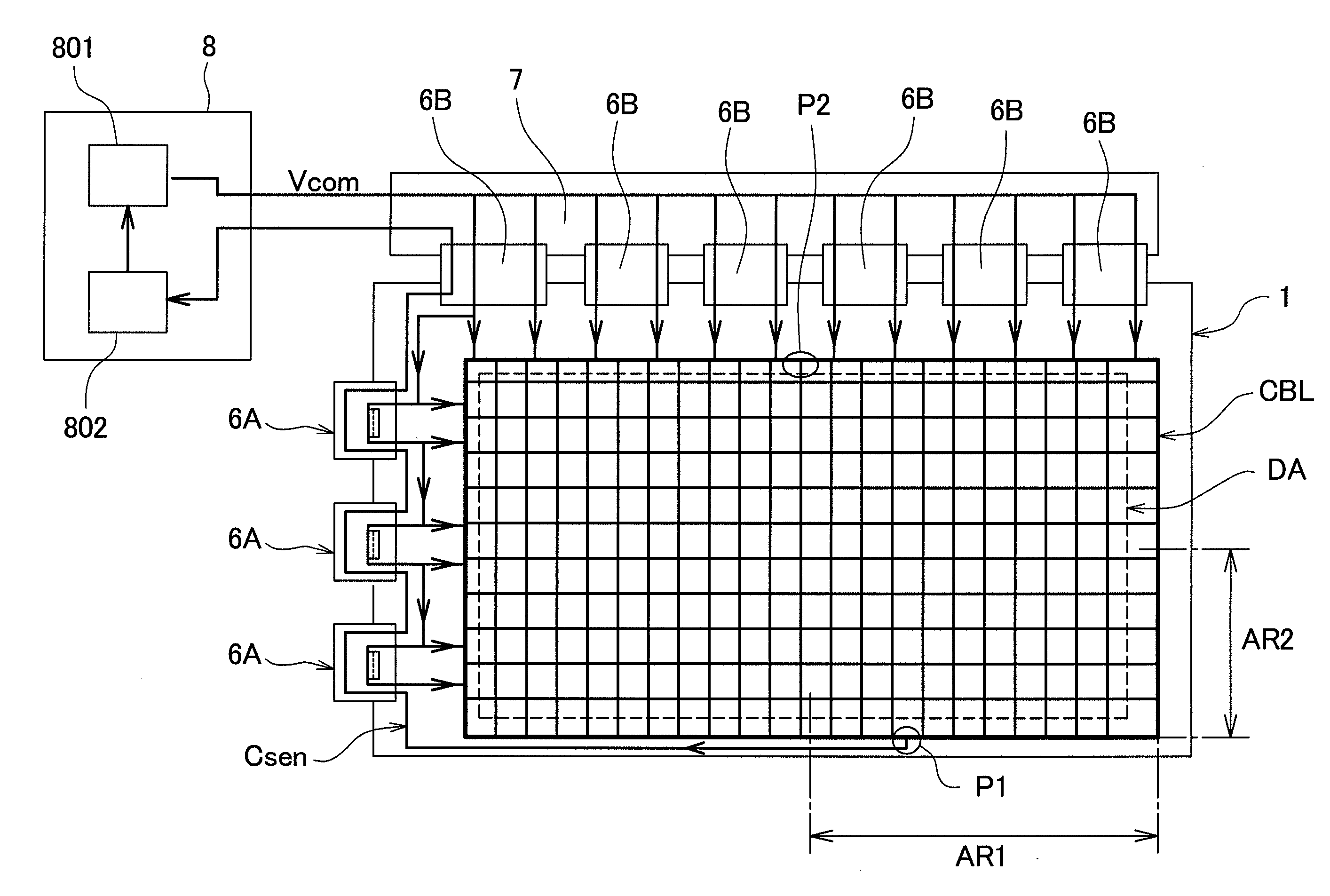
[0043]FIG. 6 is a schematic view showing the schematic constitution of a liquid crystal display device of one embodiment according to the present invention. FIG. 7 is a schematic plan view for explaining the constitution of a common bus line in a region P1 shown in FIG. 6.

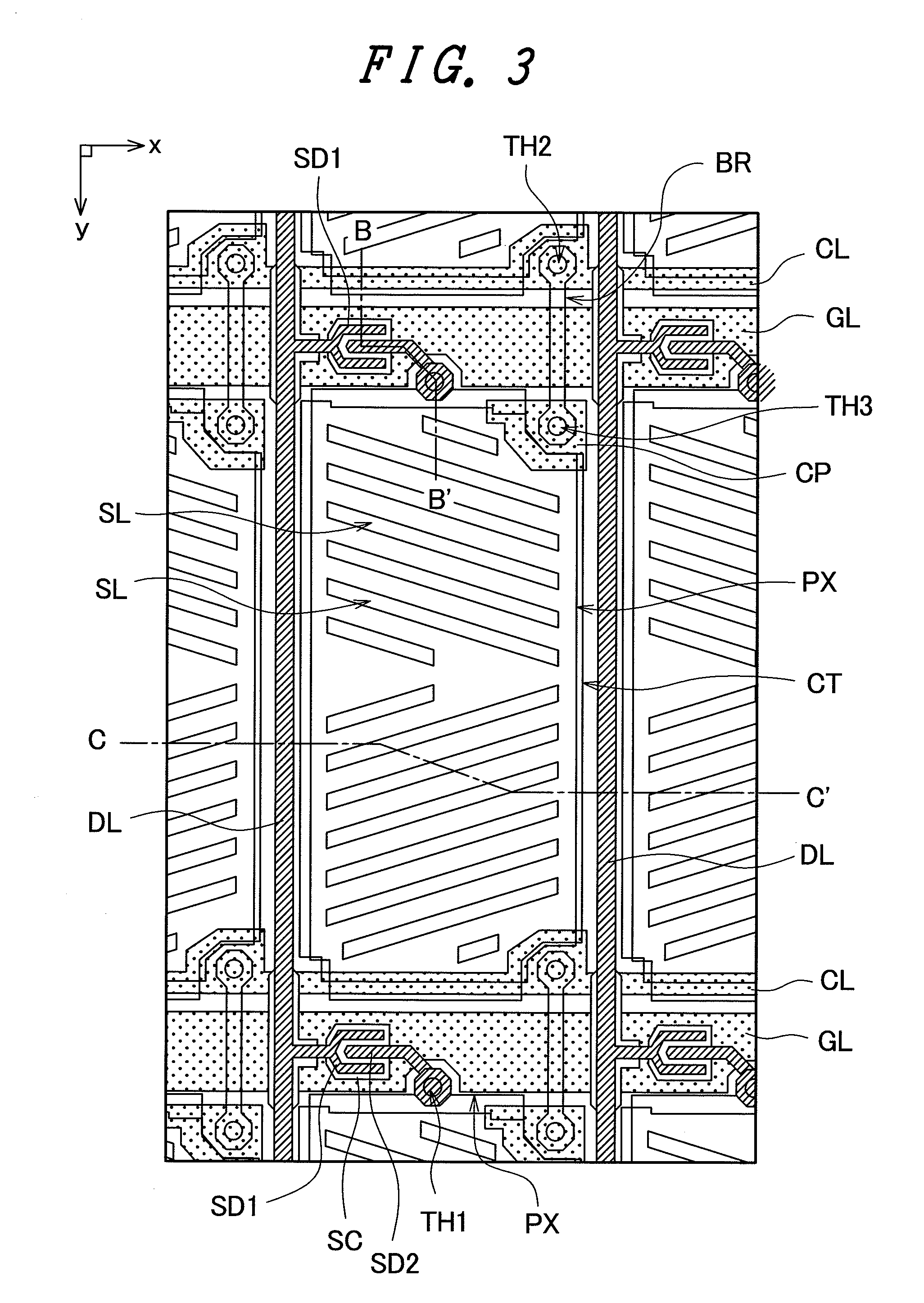
[0044]In the liquid crystal display device of this embodiment, over the TFT substrate 1 of the liquid crystal display panel, for example, common electricity supply lines which longitudinally traverse the display region DA shown in FIG. 6 and common electricity supply lines which laterally traverse the display region DA shown in FIG. 6 are arranged in a matrix array. Here, the common electricity supply lines which longitudinally traverse the display region DA are, for example, constituted of the bridge lines BR and the common electrodes CT. On the other hand, the common electricity supply lines which laterally traverse the display region DA are constituted of the common signal lines CL which are arranged in parallel...


PUM


Abstract

The present invention enhances accuracy in feedbacking a common potential applied to common electricity supply lines. On a substrate of a display device, a plurality of scanning signal lines, a plurality of video signal lines which stereoscopically intersects the plurality of scanning signal lines by way of an insulation layer, common electricity supply lines arranged in a matrix array which intersect the plurality of scanning signal lines and the plurality of video signal lines by way of the insulation layer, and a common bus line which is arranged around an approximately quadrangular display region to surround the display region annularly and is electrically connected with the common electricity supply lines are formed. The substrate includes a common sensing line which feedbacks a voltage of the common bus line to a common voltage generating circuit, and the common sensing line is connected to a side of the common bus line opposite to a side of the common bus line to which the voltage of the common potential is applied. Further, the common sensing line is configured not to stereoscopically intersect other conductive layer formed on the substrate.

Description

[0001]The present application claims priority from Japanese application JP2006-151002 filed on May 31, 2006, the content of which is hereby incorporated by reference into this application.BACKGROUND OF THE INVENTION[0002]1. Field of the invention[0003]The present invention relates to a display device, and more particularly to a technique which is effectively applicable to a liquid crystal display device adopting a lateral-electric-field driving method.[0004]2. Description of Related Art[0005]Conventionally, with respect to a liquid crystal display device which includes a liquid crystal panel formed by sandwiching a liquid crystal material between a pair of substrates, for example, there has been known a lateral-electric-field driving liquid crystal display device such as an IPS (In-Plane-System) liquid crystal display device. A liquid crystal display panel which is used in the lateral-electric-field driving liquid crystal display device forms pixel electrodes and common electrodes (...

Claims


Application Information

Patent Timeline
IPC IPC(8): G09G3/36
CPCG09G2300/0434G09G3/3655
Inventor HIRATA, MASAFUMIASHIZAWA, KEIICHIROUWATANABE, YOSHIKIIWATO, HIROAKIICHIHARA, KATSUMI
Owner PANASONIC LIQUID CRYSTAL DISPLAY CO LTD
Why Eureka
Try Eureka