Tiled Optical Fiber Display

Inactive Publication Date: 2007-12-06
MCMASTER UNIV
View PDF20 Cites 55 Cited by
  • Summary
  • Abstract
  • Description
  • Claims
  • Application Information

AI Technical Summary

Benefits of technology

[0014] The present invention provides a tiled optical fiber display device structure which includes a light emitting diode (LED) backlit liquid crystal display (LCD). Light from the LCD enters an array of optical fibers

Problems solved by technology

In many applications, this is not affordable, particularly where a large number of pixels is desired.
A major issue with this approach is the loss of light associated with t

Method used


Image

  • Tiled Optical Fiber Display
  • Tiled Optical Fiber Display
  • Tiled Optical Fiber Display

Examples


Example

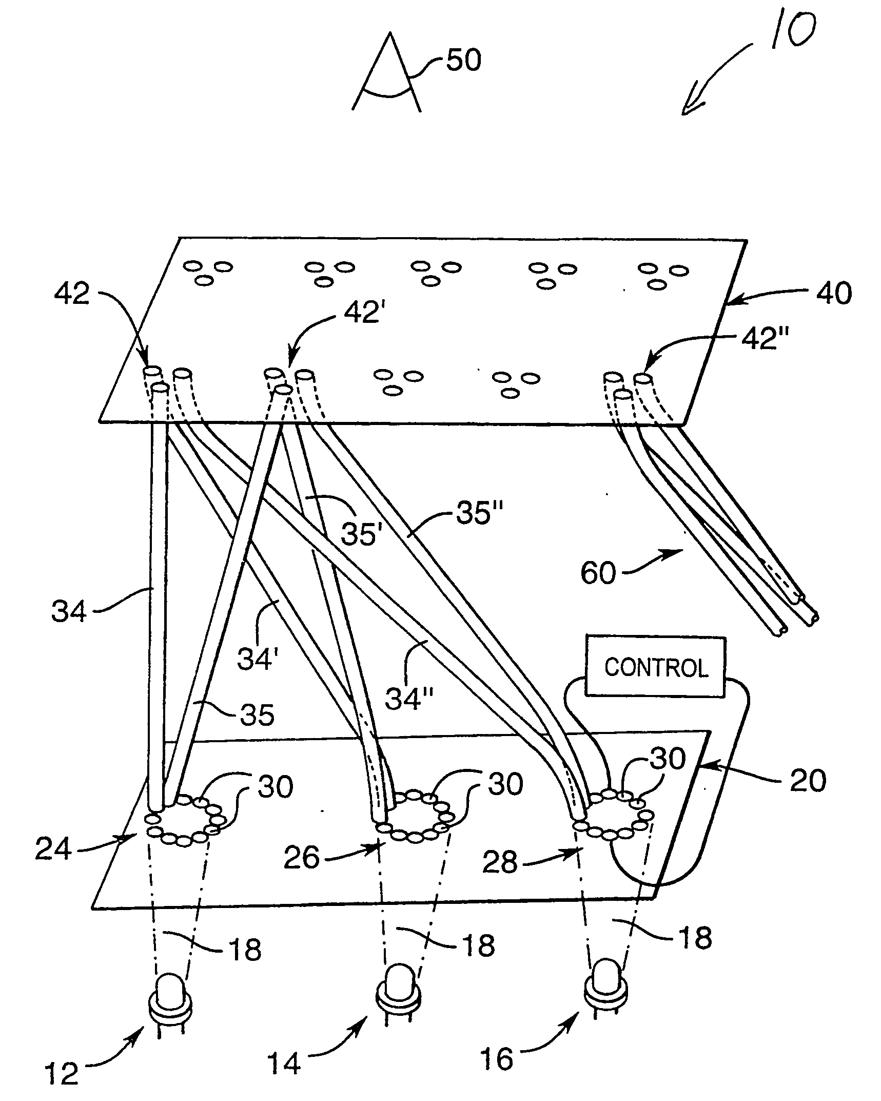
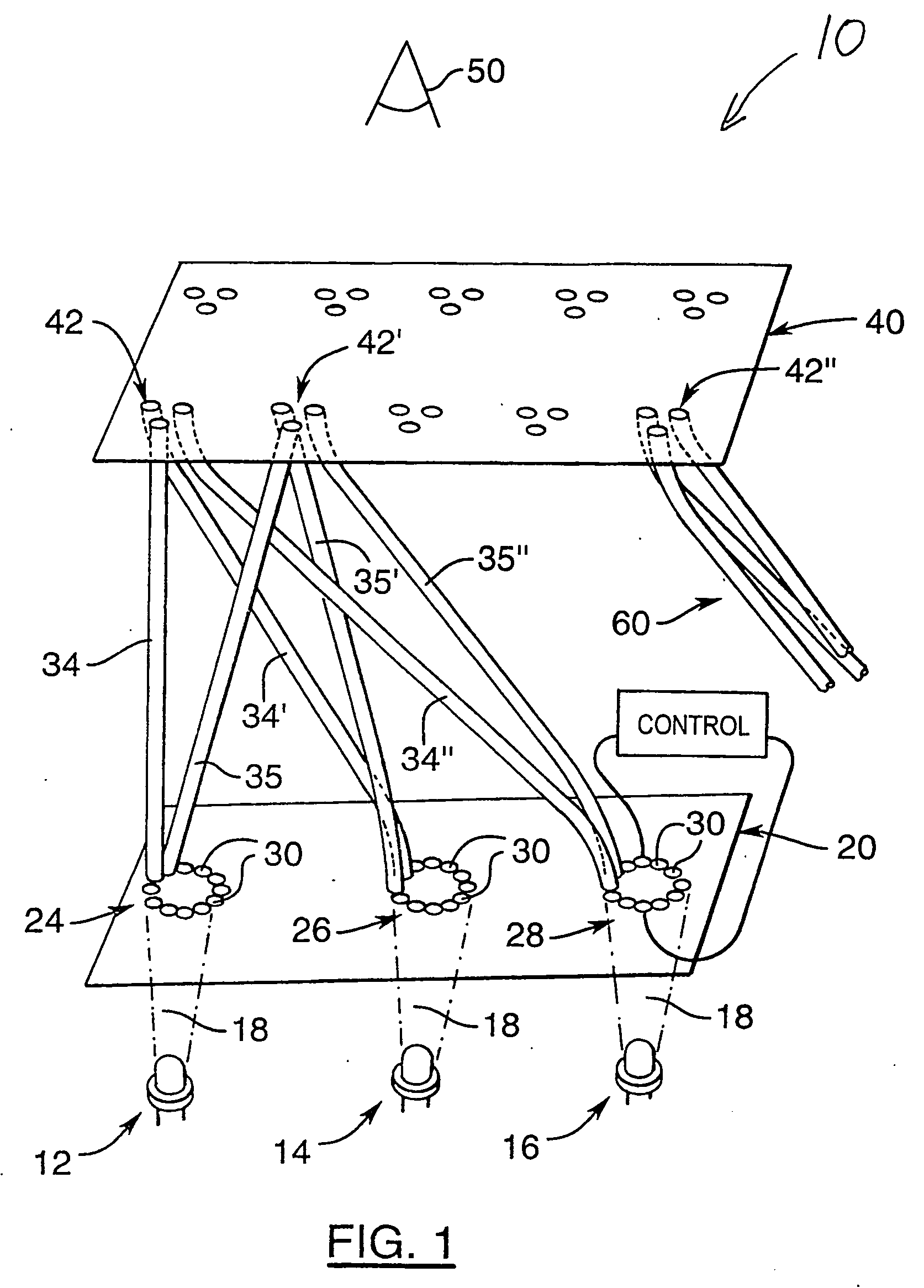
[0025] The structure and operation of the display will now be described with reference to FIG. 1, which shows an example of a display 10 constructed in accordance with the present invention. A red, a green and a blue-emitting light emitting diode (LED) at 12, 14 and 16 respectively are supplied with a steady direct electric current (DC) to provide steady illumination. Focused LED's are preferred from which a light beam is emitted in a cone 18 of a particular colour from each LED with a typical divergence angle of ˜15°. Light from each LED 12, 14, and 16 illuminates only a desired portion 24, 26 and 28 respectively of a liquid crystal display (LCD) modulator 20 so that light of only one colour from only one LED illuminates each associated portion of LCD modulator 20. The LCD modulator 20 is comprised of both polarizers and polarization-rotating LC material capable of allowing varying amounts of light to pass through the LCD modulator 20 from substantially no light to a significant am...


PUM


Abstract

The present invention provides a tiled optical fiber display device structure which includes a light emitting diode (LED) backlit liquid crystal display (LCD). Light from the LCD enters an array of optical fibers that directs the light to a viewing screen. The optical fibers eliminate the use of energy absorbing colour filters in conventional LCD's, and also enable the seamless tiling of multiple display modules.

Description

CROSS REFERENCE TO RELATED U.S. APPLICATION [0001] This patent application relates to, and claims the priority benefit from, U.S. Provisional Patent Application Ser. No. 60 / 538,501 filed on Jan. 26, 2004, which is incorporated herein by reference in its entirety.FIELD OF THE INVENTION [0002] The present invention relates to a tiled optical fiber display. BACKGROUND OF THE INVENTION [0003] Liquid crystal (LC), light emitting diode (LED) and plastic optical fibre (POF) technologies are combined in a unique way to form full colour displays. Remarkable progress in LED technology has recently enabled high efficiency red, green and blue light sources with lifetimes of 100,000 hours. These are in current use for very large outdoor video displays (diagonal size of 20 ft, for example) with pixel spacings >2 cm, where the high cost of assembling from ˜100,000 to ˜1,000,000 LEDs is warranted. (Cost from $50,000 to $1,000,000 or more.) [0004] In many applications, this is not affordable, par...

Claims


Application Information

Patent Timeline
IPC IPC(8): G02F1/133G09F9/35G09G3/36A47C19/04A47C20/08A61G7/012A61G7/015A61G7/053A61G7/10
CPCG02F1/13336G02F1/133524G09G2300/046G09G3/3413G09G3/3426G02F1/133603
Inventor KITAI, ADRIAN
Owner MCMASTER UNIV
Why Eureka
Try Eureka