Methods and apparatus for automated part positioning based on geometrical comparisons

a technology of geometric comparison and automatic positioning, applied in the field of assemblies, can solve the problems of inability to achieve accurate positioning, and inability to achieve mass properties of the target model,

Active Publication Date: 2007-12-06
THE BOEING CO
View PDF7 Cites 32 Cited by
  • Summary
  • Abstract
  • Description
  • Claims
  • Application Information

AI Technical Summary

Benefits of technology

[0007]In general, the present invention relates to a method of determining a rigid motion between two models of different types by identifying, within each model, geometrical entities having a unique characteristic, and then determining the best match with respect to that characteristic between the identified geometric entities. In doing so, the invention makes use of the fact that planar faces and linear edges are preserved during tessellation. The invention may be embodied in one form by: providing, in machine-readable form, a master model comprising ...

Problems solved by technology

This is a difficult task, however, as it is not trivial to determine the appropriate rigid body motion which will position the exact model—the master—at the position occupied by the simplified, target model.
The mass properties of the target model—center of gravity, principal axes, etc.—cannot be used to achieve this, because, as stated above, their values a...

Method used


Image

  • Methods and apparatus for automated part positioning based on geometrical comparisons
  • Methods and apparatus for automated part positioning based on geometrical comparisons
  • Methods and apparatus for automated part positioning based on geometrical comparisons

Examples


Embodiment Construction

[0014]The following detailed description is merely exemplary in nature and is not intended to limit the invention or the application and uses of the invention. Furthermore, there is no intention to be bound by any expressed or implied theory presented in the preceding technical field, background, brief summary or the following detailed description. It should be appreciated that any processing steps described as being performed by a computer system, microprocessor, or software may in fact be realized by any number of hardware, software, and / or firmware components configured to perform the specified functions. For the sake of brevity, conventional techniques and systems used in connection with computer-aided design (CAD), geometric modeling, and graph theory are not described in exhaustive detail herein.

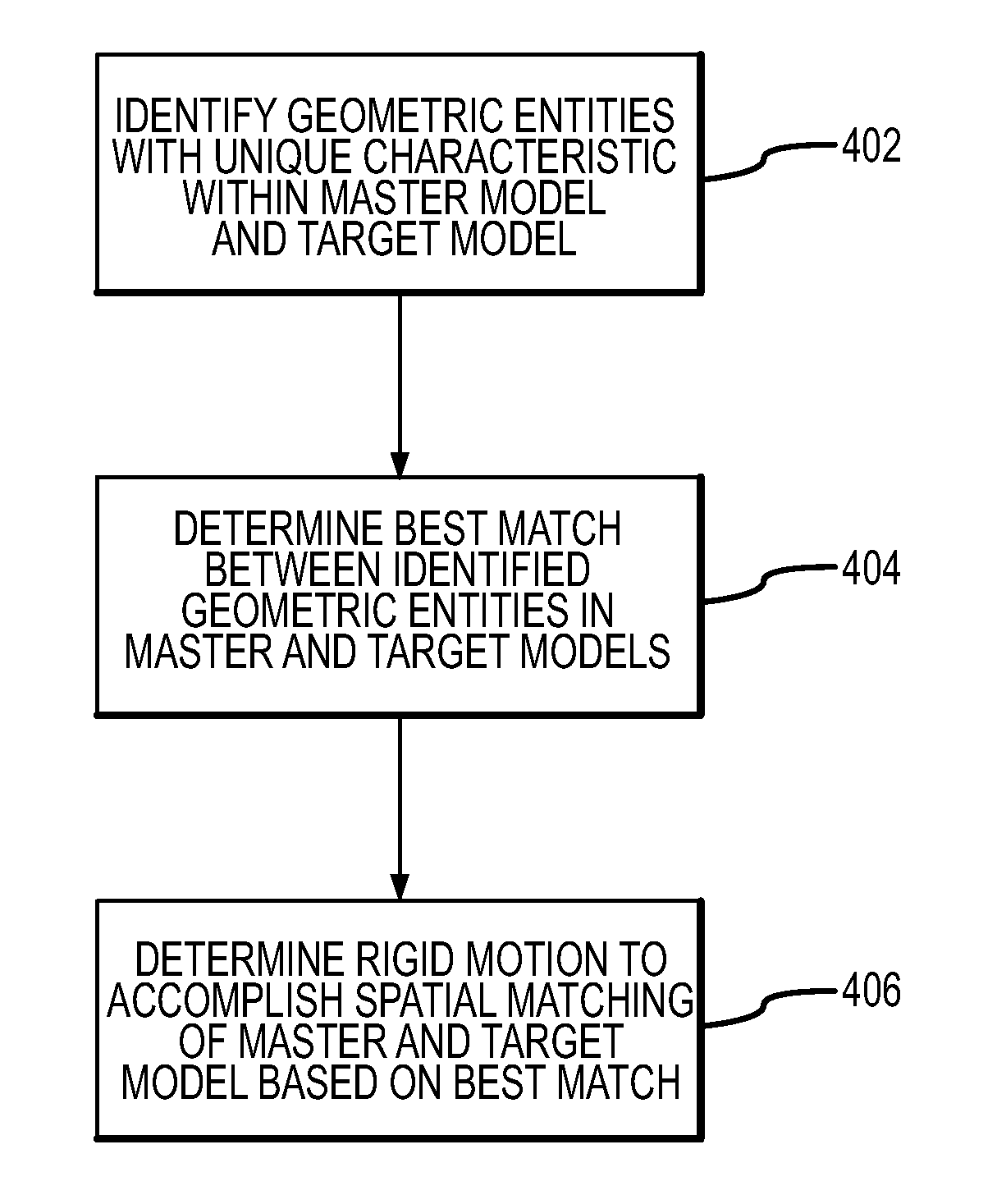
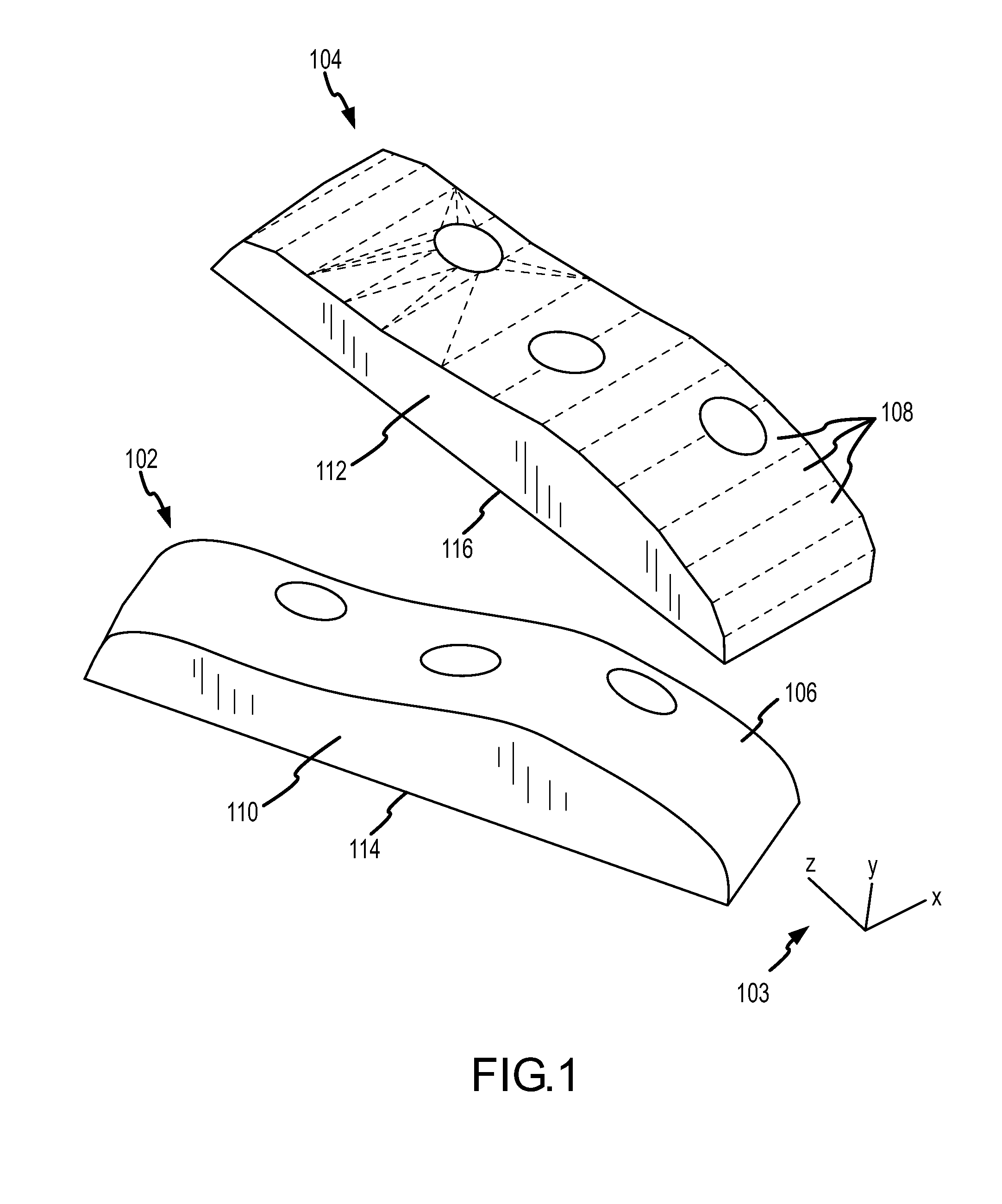
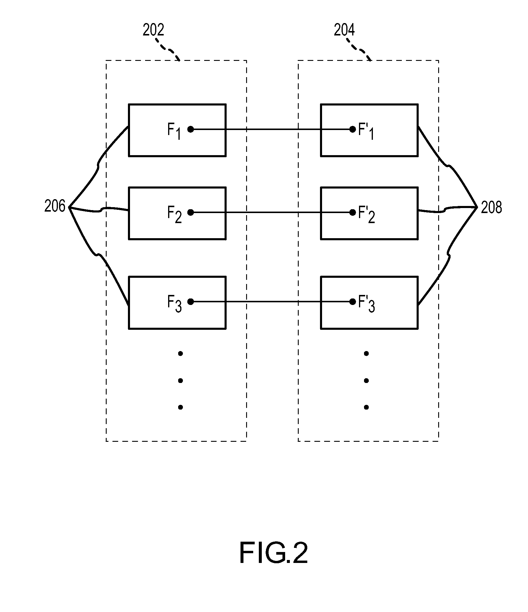
[0015]In general, the present invention relates to a method of determining a rigid motion between a first model (e.g., a “master” model of a part) and a second model (e.g., a “target” ...


PUM


Abstract

A method of determining a rigid motion between a master solid model and an approximated target model (or, more generally, between any two models having different types) includes identifying, within each model, geometrical entities having a unique characteristic, and then determining the best match between the identified geometric entities. The system provides, in machine-readable form, a master model comprising a precise definition of a three-dimensional solid and a target model comprising a simplified definition of the three-dimensional solid. Then it identifies a first set of geometric entities (e.g., planar faces) within the master model that have a unique characteristic (e.g., planar area), and identifies a second set of geometric entities in the target model that have the unique characteristic. The system then determines a best match between a member of the first set of geometric entities and a member of the second set of geometric entities using, for example, a Hungarian matching algorithm. Linear edges of matched faces are compared to determine the appropriate rigid motion.

Description

TECHNICAL FIELD[0001]The present invention generally relates to assemblies produced using computer-aided design (CAD) and, more particularly, to automated positioning of modeled parts having diverse model types.BACKGROUND[0002]Computer-aided-design (CAD) has achieved wide popularity in a number of industries, as it provides an efficient way to design and model three-dimensional solids. As a result, many organizations have large databases of models that correspond to legacy assemblies. These models vary widely in type, however, and many of these model types were designed to be compact in order to reduce storage size and computational complexity.[0003]For example, while it is common today to represent three-dimensional solids in a precise way using boundary representation (BRep), many legacy models exist only in a simplified, less precise form—e.g., as tessellated models. These tessellated models were generally derived from BRep models to save space and facilitate viewing large assemb...

Claims


Application Information

Patent Timeline
IPC IPC(8): G06T17/00
CPCG06T17/10G06T2219/2016G06T19/20G06T7/0028G06T7/33
Inventor VANDENBRANDE, JAN H.GRANDINE, THOMAS A.LUCIAN, MIRIAMMONAHAN, JOHN
Owner THE BOEING CO
Why Eureka
Try Eureka