Liquid ejecting head, method of producing the same, and liquid ejecting apparatus

a technology of liquid ejecting head and diaphragm, which is applied in the direction of printing, inking apparatus, etc., can solve the problems of reducing the adhesion area, reducing the adhesive force reducing the contact area so as to achieve easy formation and reduce the friction between the partition walls and the diaphragm. , the effect of high accuracy

Active Publication Date: 2007-12-06
SEIKO EPSON CORP
View PDF2 Cites 12 Cited by
  • Summary
  • Abstract
  • Description
  • Claims
  • Application Information

AI Technical Summary

Benefits of technology

[0025]According to the third aspect of the invention, recesses having a desired shape can be easily formed with high accuracy by anisotropic etching, and the recesse

Problems solved by technology

However, in the structure in which a recess having a width larger than the width of a pressure-generating chamber is formed on a diaphragm, the area where partition walls are in contact with the diaphragm is decreased, thereby decreasing the adhesion area.
This structure causes a problem of decreasing the adhesive force between the partition walls and the diaphragm which counters the reactive force of ink during discharge of the ink.
This structure is also disadvantageous in that the diaphragm may be separated from the partition walls when the driving of piezoelectric elements is repeatedly performed, and breaka

Method used


Image

  • Liquid ejecting head, method of producing the same, and liquid ejecting apparatus
  • Liquid ejecting head, method of producing the same, and liquid ejecting apparatus
  • Liquid ejecting head, method of producing the same, and liquid ejecting apparatus

Examples


first embodiment

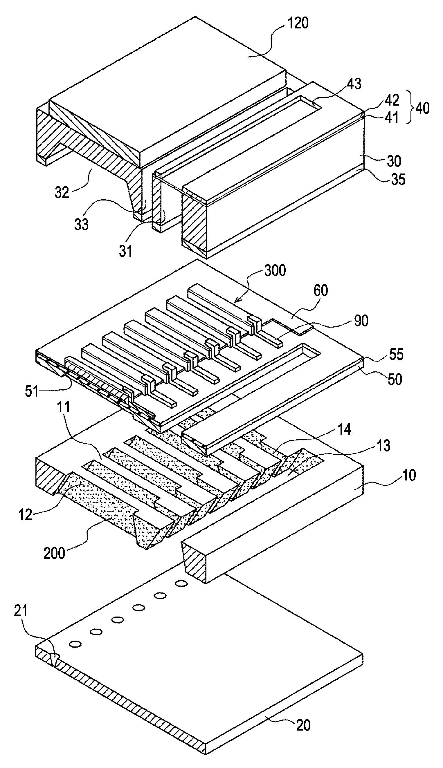
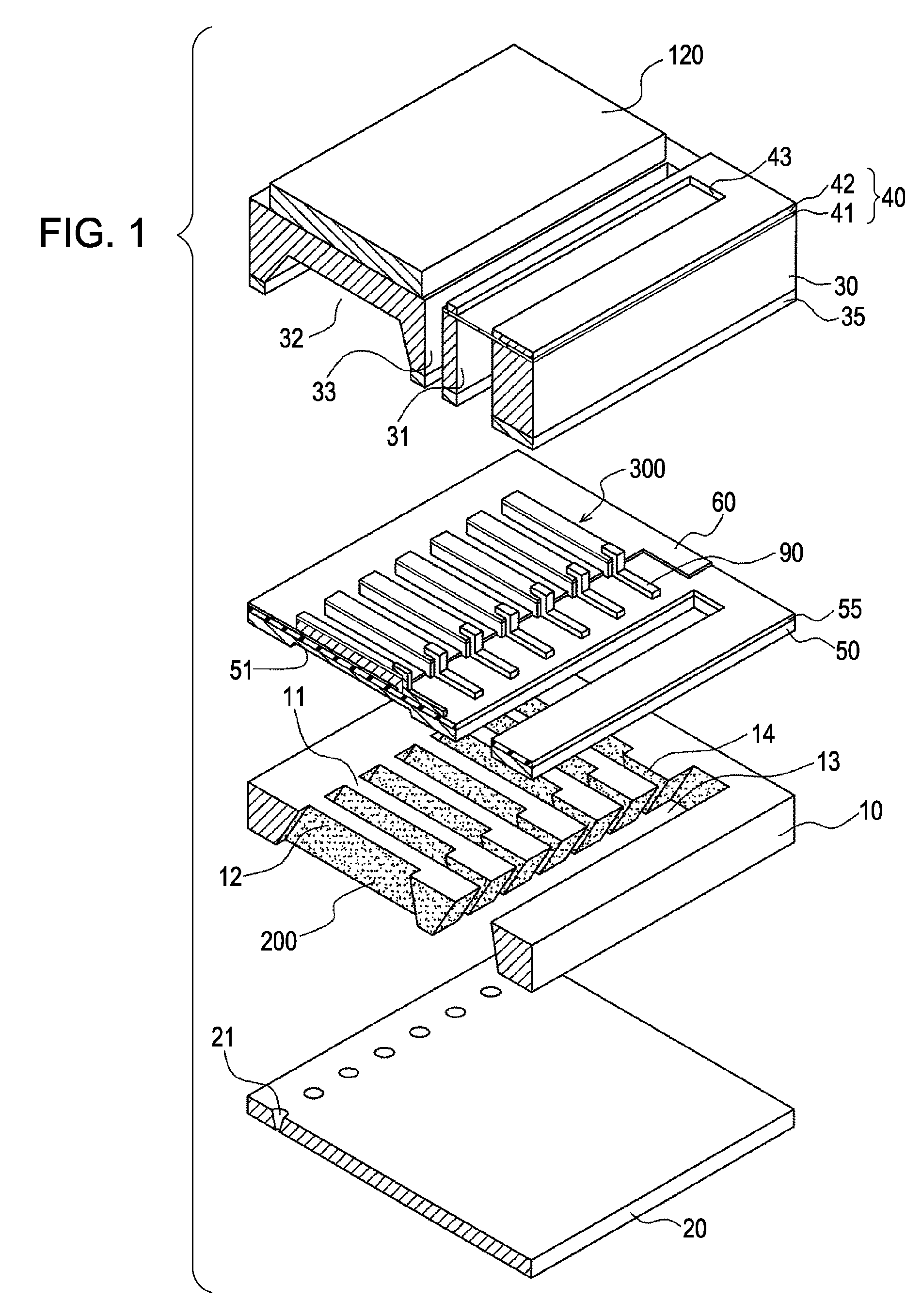
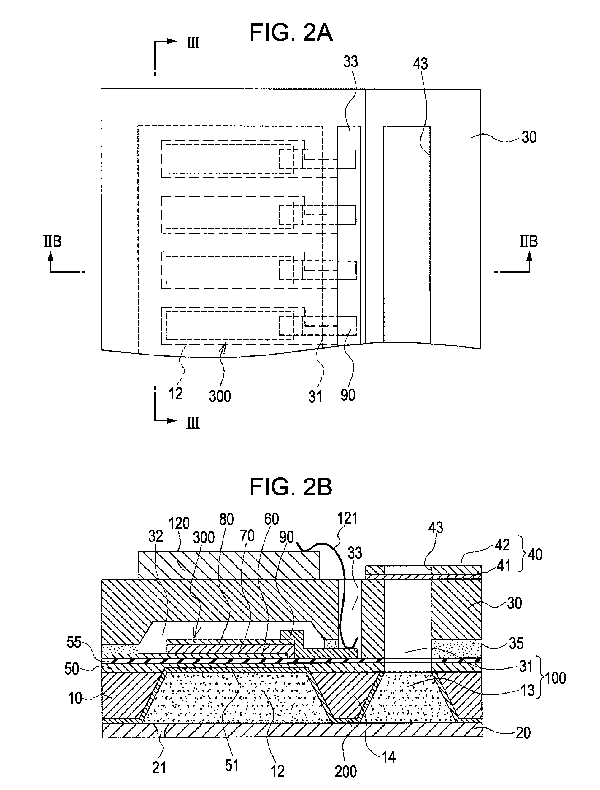
[0040]FIG. 1 is an exploded perspective view of an ink jet recording head, which is an example of a liquid ejecting head, according to a first embodiment of the invention. FIG. 2A is a plan view of the ink jet recording head shown in FIG. 1, and FIG. 2B is a cross-sectional view taken along line IIB-IIB in FIG. 2A. FIG. 3A is a cross-sectional view taken along line III-III in FIG. 2A, and FIG. 3B is a cross-sectional view of the relevant part of FIG. 3A. As shown in the figures, in this embodiment, a channel-forming substrate 10 is composed of a single-crystal silicon substrate having a crystal plane direction of (110). A silicon dioxide elastic film 50 having a thickness in the range of 0.5 to 2 μm is formed in advance on one surface of the channel-forming substrate 10 by thermal oxidation.

[0041]A plurality of pressure-generating chambers 12 separated by a plurality of partition walls 11 are arranged on the channel-forming substrate 10 in the width direction (the short-side directi...


PUM


Abstract

A liquid ejecting head includes a channel-forming substrate that communicates with nozzle orifices for ejecting a liquid and that includes a plurality of pressure-generating chambers separated by a plurality of partition walls and arranged in parallel in a direction in which a short side thereof extends; and pressure-generating elements that are provided on a surface of the channel-forming substrate, with a diaphragm therebetween, and that provide the pressure-generating chambers with a pressure change. In the liquid ejecting head, recesses that open to the side of the pressure-generating chambers are provided on areas of the diaphragm, the areas facing the pressure-generating chambers; opening edges of each of the recesses are disposed at the same positions as corners each defined by an inner surface of the corresponding partition wall, the inner surface defining a side surface of the pressure-generating chamber, and a surface of the partition wall that is joined to the diaphragm; and side surfaces of each of the recesses form inclined surfaces that are inclined so that the width of the recess at the bottom surface of the recess is smaller than the width of the recess at the opening edges of the recess.

Description

[0001]The entire disclosure of Japanese Patent Application No. 2006-156566, filed Jun. 5, 2006 is expressly incorporated by reference herein.BACKGROUND[0002]1. Technical Field[0003]The present invention relates to a liquid ejecting head that ejects a liquid from nozzle orifices, a method of producing the liquid ejecting head, and a liquid ejecting apparatus, and in particular, to an ink jet recording head that discharges ink as a liquid, a method of producing the ink jet recording head, and an ink jet recording apparatus.[0004]2. Related Art[0005]Various types of ink jet recording heads, which are liquid ejecting heads used for printers, facsimile machines, copy machines, or the like utilizing a mechanism for discharging ink droplets are known. In an example of such an ink jet recording head, a part of each of pressure-generating chambers communicating with nozzle orifices is composed of a diaphragm, and the shape of this diaphragm is changed by a displacement of piezoelectric eleme...

Claims


Application Information

Patent Timeline
IPC IPC(8): B41J2/04
CPCB41J2/14233B41J2/161B41J2/1623B41J2/1629B41J2202/11B41J2/1645B41J2002/14241B41J2002/14419B41J2002/14491B41J2/1632
Inventor SHIMADA, MASATO
Owner SEIKO EPSON CORP
Why Eureka
Try Eureka