
High-order aberration correction for optimization of human visual function

a human visual function and optimization technology, applied in the field of human visual function optimization, can solve the problems of large 1.2-diopter sphere error, no mechanism for changing the amount of high-order aberrations, and represented optical errors, so as to improve contrast sensitivity, low-contrast visual acuity and vernier acuity, the effect of improving contrast sensitivity

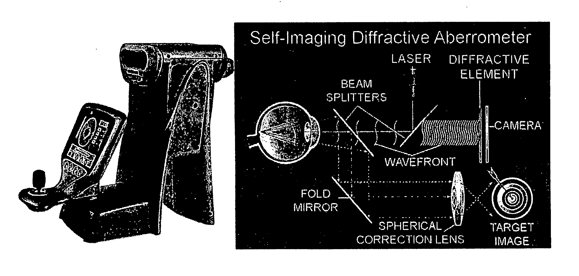
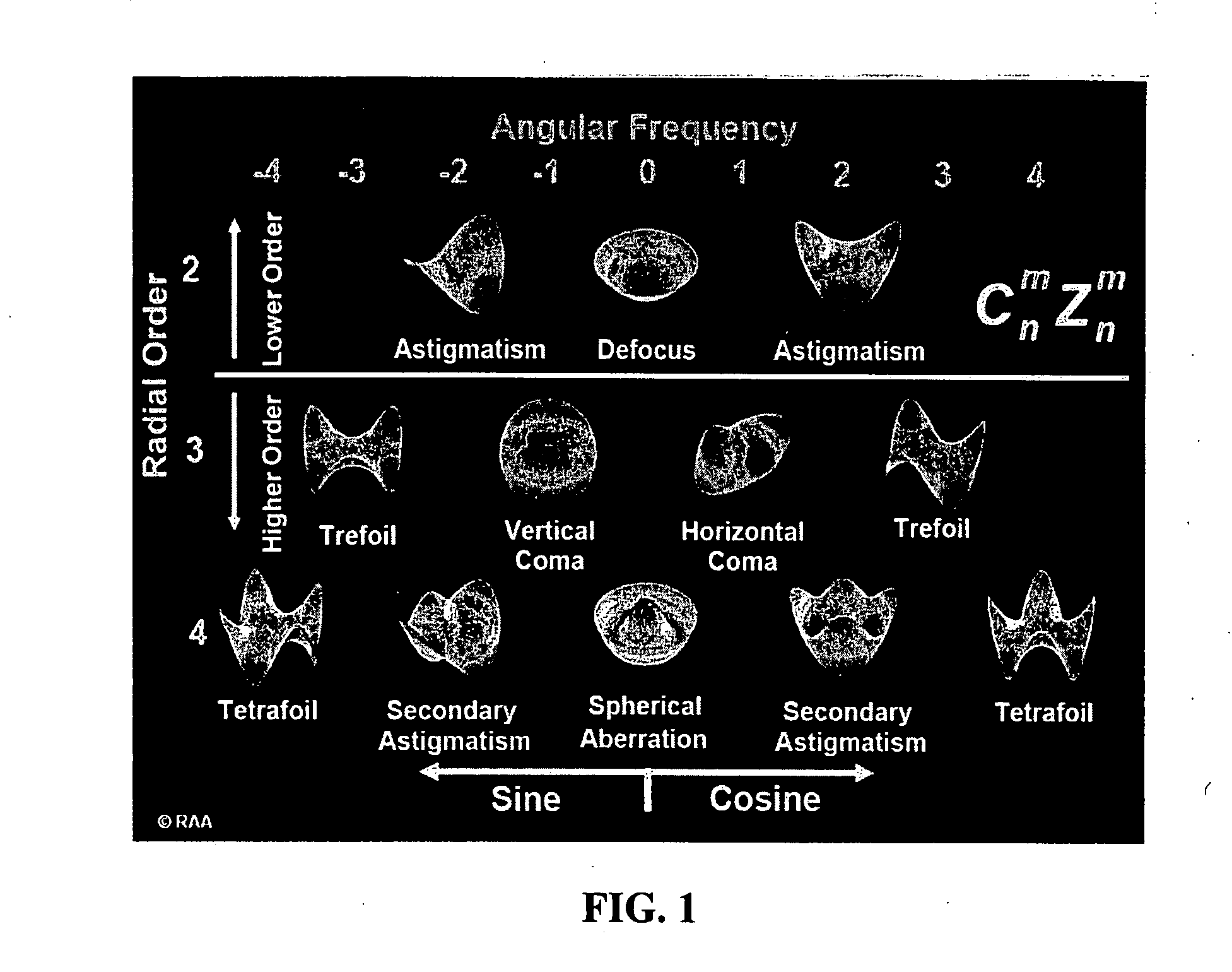
Active Publication Date: 2007-12-06
ESSILOR INT CIE GEN DOPTIQUE
View PDF18 Cites 27 Cited by
  • Summary
  • Abstract
  • Description
  • Claims
  • Application Information

AI Technical Summary

Benefits of technology

The present invention provides a way to improve the clarity and sensitivity of using various optical devices such as binoculars, rifle scopes, telescopes, microscopes, night vision goggles, and laser eye protection devices. By correcting and optimizing high-order aberrations, these devices can enhance the contrast sensitivity and low-contrast visual acuity, making them easier to use and improving performance in both military and civilian settings.

Problems solved by technology

However, in almost any normal eye there are optical errors represented by leads or lags in the wavefront, and in the analogy, hills and valleys in the drum surface.
For comparison, to achieve a similar RMS wavefront error in a 3mm daytime pupil requires a 1.2-diopter sphere error, which is considered large.
Whereas residual sphere error can be nullified via the variable focusing power of the lens through the process of accommodation, the eye has no mechanism for changing the amount of high-order aberrations.
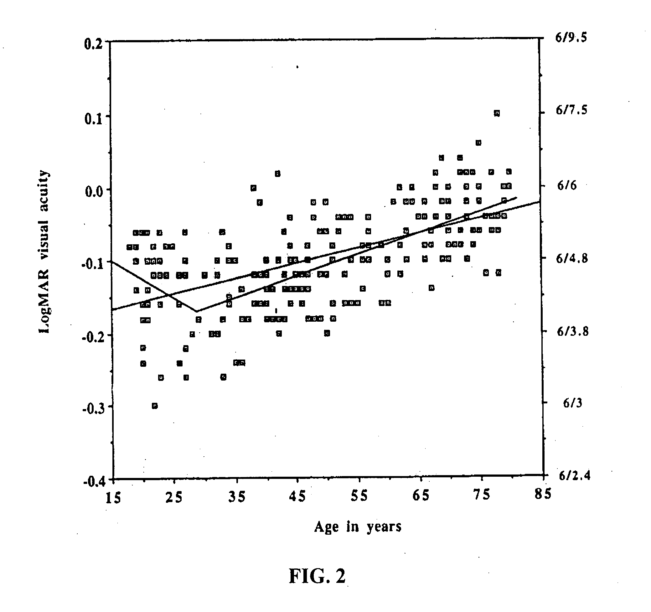
In low-light conditions when the pupil diameter and the level of high-order aberrations both increase, contrast sensitivity begins to degrade.
One is that it may no longer be possible to detect certain low-contrast objects which are important in for example driving, hunting and military applications.
The other problem is that even if an object can be detected, the detection and recognition process will take longer.
In a low contrast situation, the letters would be even more difficult to recognize, and of course, there are many other possible aberrations besides coma.
If sphere and cylinder are not also optimally corrected, there will in addition be severe contrast losses due to low-order aberrations.

Method used


Image

  • High-order aberration correction for optimization of human visual function
  • High-order aberration correction for optimization of human visual function
  • High-order aberration correction for optimization of human visual function

Examples


Embodiment Construction

[0033] Currently, aggressive high-order aberration correction can only be implemented over a restricted field-of-view. Therefore devices that naturally operate with a restricted field-of-view are ideal candidates for this type of optical correction. Another category where high-order aberration optimization is expected to be of major benefit involves low light conditions where the pupil size is significantly increased. Optical aberrations generally increase dramatically with pupil diameter and can therefore have a larger impact on vision. Four modes of high-order wavefront correction in devices are included in the present invention. They are the following: [0034] Binoculars [0035] Rifle Scopes [0036] Night Vision Devices [0037] Laser Eye Protection Spectacles / Goggles

[0038] The first three naturally employ a restricted field-of-view. The last two modes intrinsically involve reduced levels of light entering the eye, forcing increased pupil sizes in all conditions. The first two modes ...


PUM


Abstract

The present invention relates to the optimization of human visual function by correcting and / or optimizing high-order optical aberrations in high performance optical devices. The optimization is particularly useful for high performance devices used under low light conditions such as binoculars, rifle scopes, telescopes, microscopes, night vision goggles and laser eye protection devices.

Description

CROSS-REFERENCE TO RELATED APPLICATIONS [0001] The present application claims the benefit of priority under 35 U.S.C. § 119(e) to U.S. Provisional Patent Application Ser. No. 60 / 800,988. The contents of this document are incorporated herein by reference.FIELD OF THE INVENTION [0002] The present invention relates to the optimization of human visual function by correcting and / or optimizing high-order optical aberrations. The optimization is particularly useful for high performance activities especially under low light conditions. BACKGROUND OF THE INVENTION [0003] The wavefront error of the human eye is analogous to the surface of a drum. The diameter of the drum represents the diameter of the pupil of the eye. If there were no aberrations, the surface of the drum would be flat. However, in almost any normal eye there are optical errors represented by leads or lags in the wavefront, and in the analogy, hills and valleys in the drum surface. Any smooth surface over a circular aperture ...

Claims


Application Information

Patent Timeline
Patent Type & Authority Applications(United States)
IPC IPC(8): G02C7/06G02C7/10
CPCG02B25/001G02C2202/22G02C7/02G02B27/0025
Inventor JETHMALANI, JAGDISH M.DREHER, ANDREAS W.SVERDRUP, LAWRENCE H.
Owner ESSILOR INT CIE GEN DOPTIQUE
Learn More