Method and device for position sensing of an optical component in an imaging system

a technology of optical components and optical position sensors, applied in the direction of cameras, instruments, printers, etc., can solve the problems of distorted significant changes in the shape of light spots on image sensors

Active Publication Date: 2007-12-06
NOKIA TECHNOLOGLES OY
View PDF1 Cites 10 Cited by
  • Summary
  • Abstract
  • Description
  • Claims
  • Application Information

AI Technical Summary

Benefits of technology

[0005]The present invention uses a light beam to illuminate a spot on a lens element which is shifted along the optical axis of the imaging system for auto-focus or optical zoom purposes. The light beam is arranged such that the reflected light beam from the lens element encounters a spot on the image sensor. The spot on the image sensor is read out in a signal processor. As the lens element is shifted along the optical axis, the spot on the image sensor is moved accordingly. Based on the moving distance of the spot on the image sensor, the signal processor determines the shifting distance of the lens element and hence the position of the lens element. Based on the shifting distance of the lens element, a control module is used to adjust the lens position along the optical axis to achieve the desired focusing or zooming effects. The control module also controls the driving of the light beam such that the light beam is turned on only between image frames for lens position sensing.

Problems solved by technology

It is possible that the light spot on the image sensor is distorted due to reflection and that the shape of the light spot on the image sensor changes considerably due to lens shifting.

Method used


Image

  • Method and device for position sensing of an optical component in an imaging system
  • Method and device for position sensing of an optical component in an imaging system
  • Method and device for position sensing of an optical component in an imaging system

Examples


Embodiment Construction

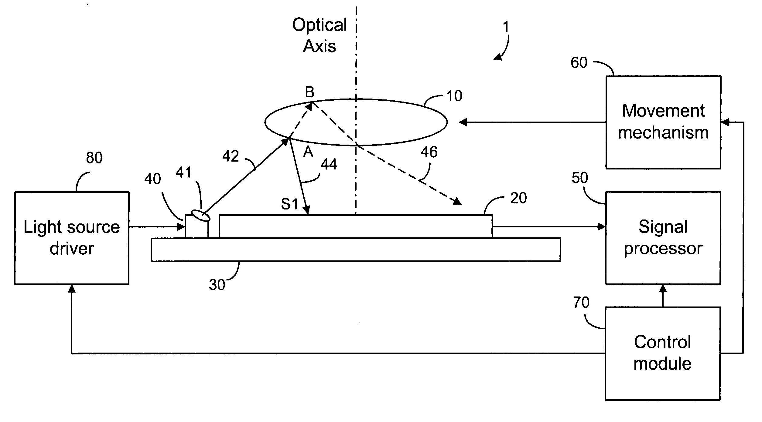
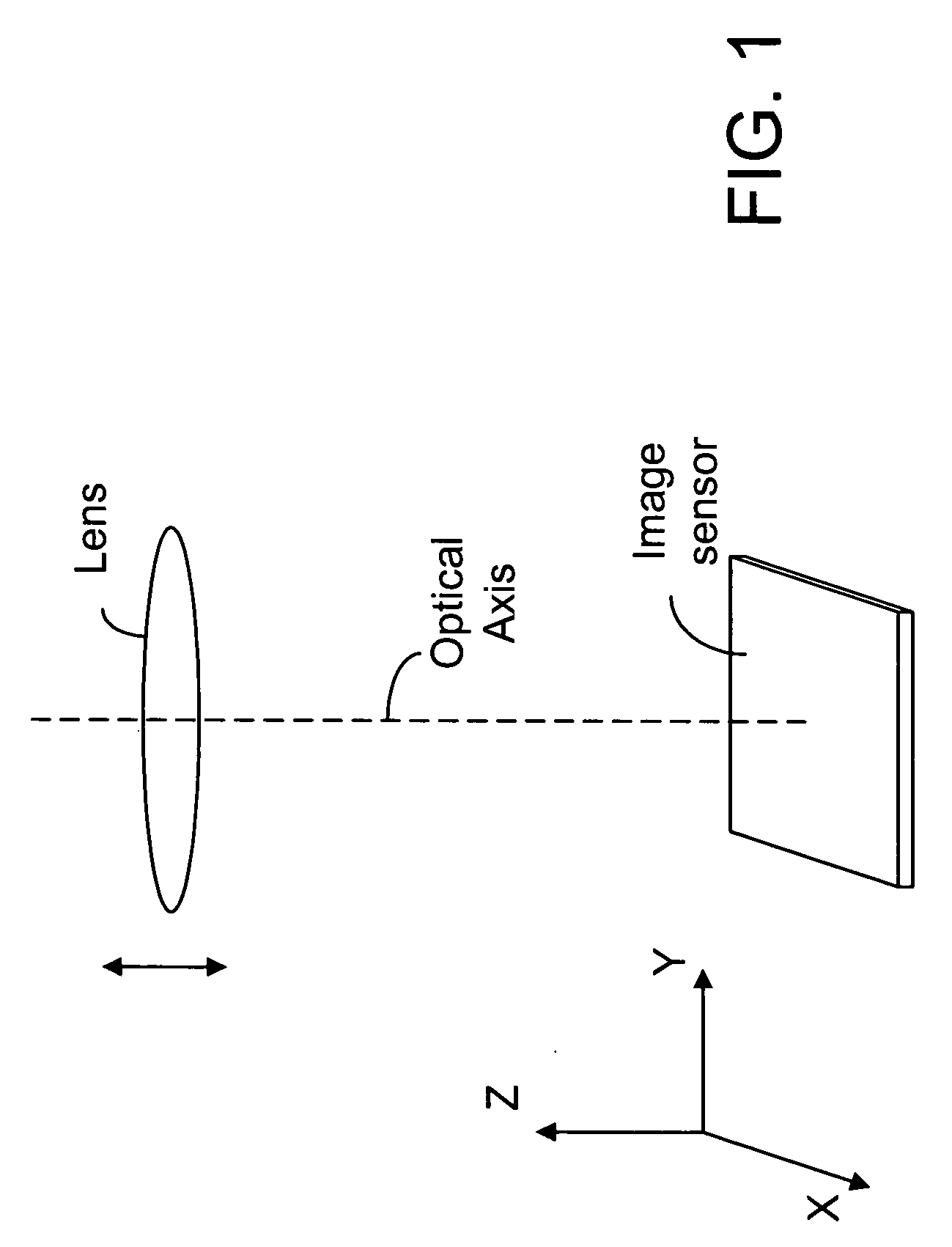
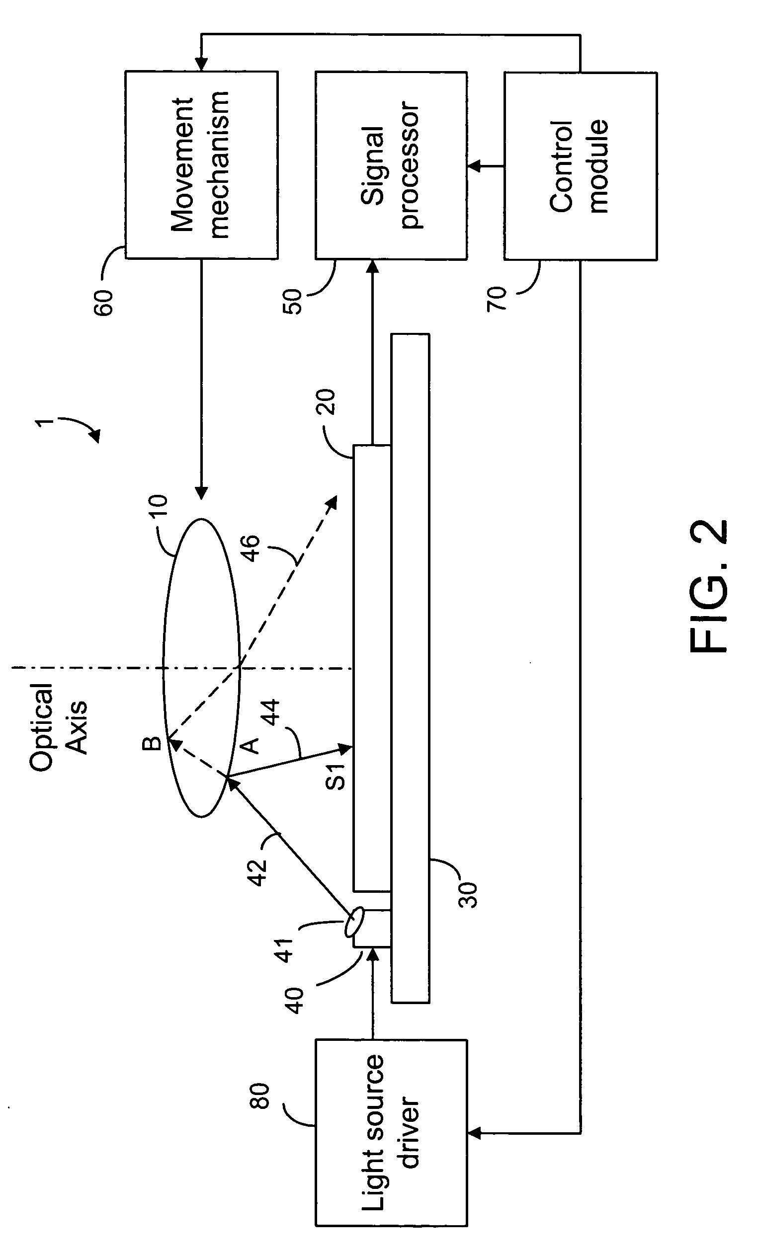
[0014]Imaging applications such as auto-focus lens systems and optical zoom systems require high precision in position sensing. In such applications, at least one lens element is moved along the optical axis of the imaging system so as to change the focal plane of the lens or the magnification of the image formed on an image sensor. As shown in FIG. 1, the movement of the lens element is substantially along the optical axis which is parallel to the Z axis. The image sensor is located in an image plane which is substantially parallel to the XY plane. The imaging system may have one or more stationary lens elements as depicted in dotted lines.

[0015]In auto-focus or optical zoom applications, it is required to determine the position of the lens element relative to a reference point or a home position. According to the present invention, a light beam is used to illuminate a spot on the surface of the lens element such that the reflected light beam from the lens surface encounters a spot...


PUM


Abstract

A light beam is used to illuminate a spot on a lens element which is shifted along the optical axis of an imaging system for auto-focus or optical zoom purposes. The light beam is arranged such that the reflected light beam from the lens element encounters a spot on the image sensor. The spot location on the image sensor is determined by a signal processor. As the lens element is shifted along the optical axis, the spot location changes accordingly. Based on the moving distance of the spot, the signal processor determines the shifting distance of the lens element and hence the position of the lens element. Based on the shifting distance of the lens element, a control module is used to adjust the lens position along the optical axis to achieve the desired focusing or zooming effects.

Description

FIELD OF THE INVENTION[0001]The present invention relates generally to optical position sensing in an imaging system and, more particularly, to position sensing for auto-focus optics and / or an optical zoom module in the imaging system.BACKGROUND OF THE INVENTION[0002]Auto-focus optical systems require high precision in position sensing. In general, needed accuracy is in the order to a few microns. Sensor output linearity and immunity to external disturbances is important. Furthermore, the operation mode for position sensing also requires non-contact operation to avoid mechanical wear. When considering optics for use in a small electronic device, such as mobile phone, the size and cost of the optical sensing components and the suitability to mass production are important issues.[0003]Typically, position determination in a commercial auto-focus module is carried out by counting stepper motor steps. For that purpose, the motor can have an embedded position encoder. In order to reduce t...

Claims


Application Information

Patent Timeline
Patent Type & Authority Applications(United States)
IPC IPC(8): G03B27/52G02B7/08G02B7/28G03B13/32G03B13/36
CPCG01S17/48G02B7/08G03B13/36G03B3/06G03B3/02
Inventor VIINIKANOJA, JARKKO
Owner NOKIA TECHNOLOGLES OY
Why Eureka
Try Eureka