Automatic additive dispensing assembly

a technology of additive dispensing and assembly, which is applied in the direction of water installations, lavatory sanitory, construction, etc., can solve the problems of insufficient retention time, inability to place additives, and difficulty in providing cleanser, deodorant, disinfectant and/or like additives to the flush water of the toilet fixture, etc., and achieves the effect of sufficient retention tim

Inactive Publication Date: 2006-09-26
KORF RABBI ABRAHAM
View PDF18 Cites 9 Cited by
  • Summary
  • Abstract
  • Description
  • Claims
  • Application Information

AI Technical Summary

Benefits of technology

[0011]The present invention is directed towards an automatic additive dispensing assembly for use with a toilet fixture which does not have an accessible flush tank, such as a commercial type toilet bowl or urinal, wherein a cleanser, deodorant, disinfectant and / or like additive is retained within at least a portion of the flush water prior to at least that portion of flush water passing into the toilet bowl or urinal, along with an additional amount of flush water necessary for a flushing operation. As such, the entire volume of the flush water that passes into the toilet bowl or urinal will be affected by the additive, and will impart the desired cleansing, deodorizing, disinfecting and / or other desired effect.
[0012]The additive, either in the form of a cleanser, deodorant, disinfectant, etc., is disposed in a retention chamber, the additive comprising any of a variety of conventional solid or liquid forms. The structure of the retention chamber is such as to readily receive the additive, such as a water dissolvable solid or liquid material. A portion of the flush water is retained within the retention chamber for a period of time at least equal to the time between flushing operations, thus providing sufficient retention time for the additive to be mixed into the first portion of the flush water. Subsequently, activation of the flush handle or like activating means will cause a second portion of the flush water to pass from the conventional pressurized water supply through a supply pipe and into the retention chamber, thereby displacing the now concentrated first portion of the flush water retained therein, as well as providing an additional amount of flush water as is required for a flushing operation. Specifically, this will cause an overflow of the concentrated first portion of the flush water from within the retention chamber, as the supply pipe for the second portion of the flush water is structured to discharge into and displace the first portion of the flush water from the retention chamber, as well as an amount of the second portion of the flush water which also flows into and out of the retention chamber during a flushing operation. The supply pipe outlet is preferably positioned in the retention chamber thereby displacing the concentrated first portion of the flush water additive which overflows into an outer container and directly therefrom into the toilet bowl or urinal for cleansing, deodorizing, disinfecting, etc.

Problems solved by technology

In most commercial toilet and urinal fixtures, however, there is no mechanism to place an additive such that it may be retained to mix into any portion of the flush water prior to a flushing operation.
It is, thus, recognized as being more difficult to provide cleanser, deodorant, disinfectant and / or like additive to the flush water of a toilet fixture without a flush tank since the supply pipe which discharges water to the interior of the toilet bowl or urinal is connected directly to a pressurized water supply structured to force flush water directly into the toilet bowl or urinal.
The supplying of a preferred additive to such an assembly therefore presently requires expensive modification of the plumbing and / or a replacement of the connection of such plumbing to the pressurized water supply system.
However, none of these patents provide for sufficient retention time of an additive with at least a portion of the flush water to assure that an effective concentration of the additive is mixed into any portion of the flush water prior to discharge into the toilet bowl or urinal during a flush operation.
However, the effectiveness of such charges is limited due to the lack of contact time with the flush water such as is required to assure an effective concentration of the additive in the flush water.
To overcome the disadvantages of prior devices, expensive assemblies have been suggested, as in the aforementioned U.S. patents, however, such expensive assemblies comprise numerous components which operate as a machine and, as such, require relatively high initial and maintenance costs.

Method used


Image

  • Automatic additive dispensing assembly
  • Automatic additive dispensing assembly
  • Automatic additive dispensing assembly

Examples


Embodiment Construction

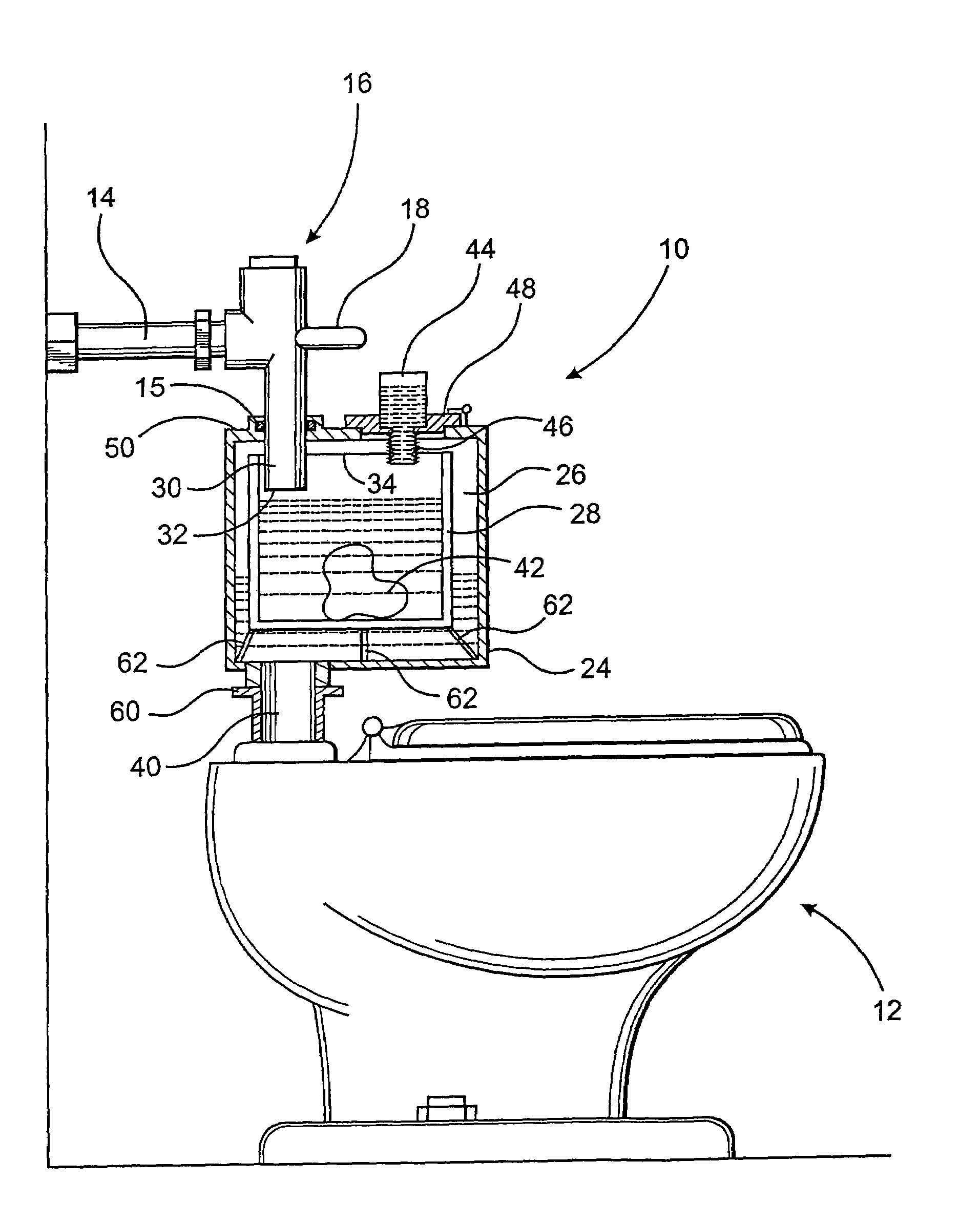
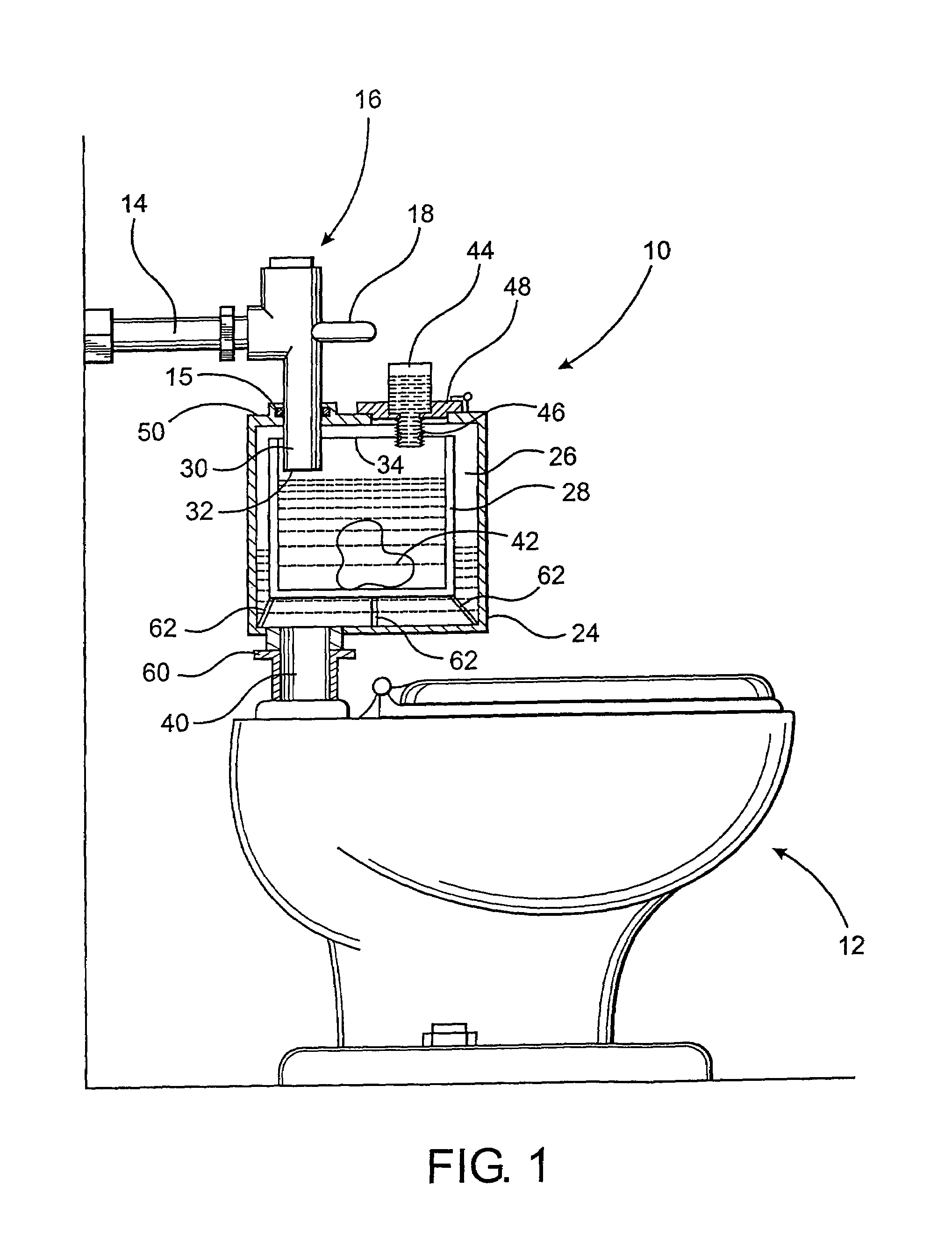
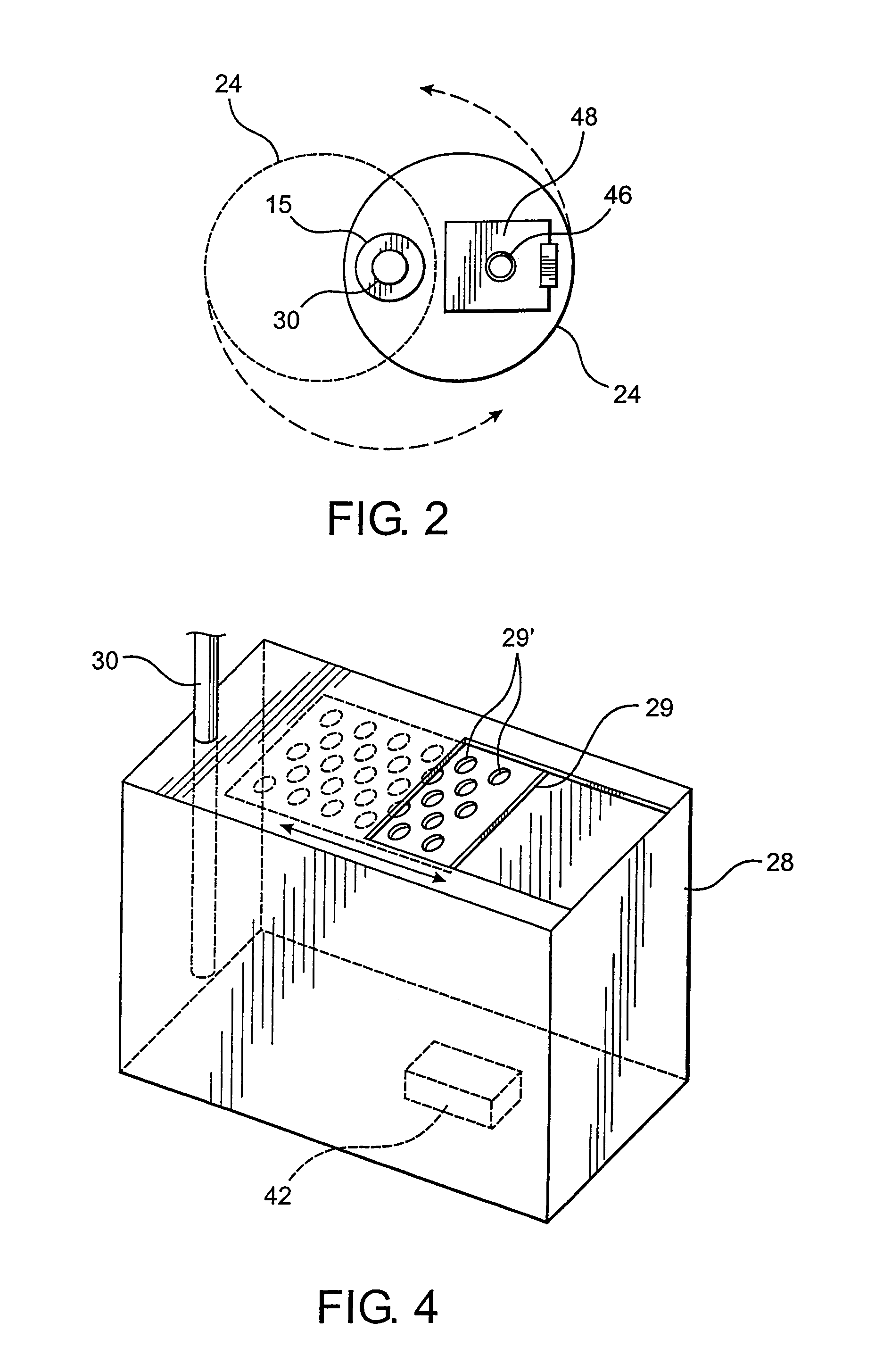
[0019]As shown in the figures, the present invention is directed towards an automatic additive dispensing assembly, generally indicated as 10, structured to disperse an additive such as a cleanser, deodorant, disinfectant, etc., into at least a portion of the flush water prior to discharge into a toilet bowl 12 or urinal 12′.

[0020]In a toilet fixture of the type represented in FIGS. 1 and 3, wherein a flush tank is not present, water flows directly from a conventional pressurized water supply into the toilet 12 or urinal 12′ via a connecting conduit 14 through which water flow is regulated by a flush valve 16. The flush valve 16 may be activated by a handle or lever 18, or it may be automatically activated, such as by an electronic eye or other motion type sensor. As will be appreciated, when the flush valve 16 is activated to open in a standard commercial toilet fixture, the entire volume of the flush water passes directly from the conventional pressurized water supply into the toi...


PUM


Abstract

A dispensing assembly structured to automatically add or dispense cleanser, deodorant, disinfectant and/or like additive to a toilet bowl or urinal, particularly of the type used in commercial applications which are normally connected to a pressurized water supply for flushing without the presence of an accessible flush tank, as is present in most domestic toilet fixtures. The assembly comprising a retention chamber disposed in fluid communication between a pressurized water supply pipe and the toilet bowl or urinal and structured to retain the additive in contact with at least a first portion of the flush water. The outlet of the pressurized water supply pipe is structured to discharge a second portion of the flush water into the retention chamber thereby displacing the first portion of the flush water from the retention chamber into the toilet bowl or urinal and providing the additional water necessary during a flushing operation.

Description

BACKGROUND OF THE INVENTION[0001]1. Field of the Invention[0002]This invention relates to an automatic additive dispensing assembly structured for use with a toilet fixture which is normally connected to a pressurized water supply for flushing without the presence of an accessible flush tank, such as, by way of example, a commercial toilet bowl or urinal. The assembly is structured to permit cleanser, deodorant, disinfectant and / or like additives to be automatically dispensed into the toilet bowl or urinal with the flush water concurrently to a flushing operation, and activated thereby. The additive may be provided in solid or liquid form, as are commercially available, such that the additive is effectively mixed into at least a first portion of the flush water, prior to the flushing operation.[0003]2. Description of the Prior Art[0004]In most modern-day commercial toilet fixtures, such as a sit-down toilet or a stand-up urinal, the flush water is provided directly from a supply pip...

Claims


Application Information

Patent Timeline
Patent Type & Authority Patents(United States)
IPC IPC(8): E03D9/02
CPCE03D9/031E03D2009/024
Inventor KORF, RABBI ABRAHAM
Owner KORF RABBI ABRAHAM
Why Eureka
Try Eureka