Low Normal Force Retracting Device Comprising a Microtextured Surface

a micro-textured surface and retracting device technology, applied in the field of surgical retracting devices comprising micro-textured surfaces, can solve problems such as trauma to retracted organs, and achieve the effect of reducing potential damage to objects and low friction

Active Publication Date: 2017-04-06
BVW HLDG
View PDF24 Cites 9 Cited by
  • Summary
  • Abstract
  • Description
  • Claims
  • Application Information

AI Technical Summary

Benefits of technology

[0020]According to a further aspect of the invention, a Type I or a Type II retraction device may be provided, when in its first state prior to actuation, with markings on its surface to aid proper orientation prior to actuation or similar markings intended to indicate regions of different surface texture. According to a further aspect of the invention, a Type I or a Type II retraction device can possess a corrugated surface wherein one configuration of the corrugation provides an adhesive Wenzel-Cassie surface and in another configuration of the corrugation provides a low friction Cassie-Baxter surface. This feature may be used to release a retracted object in a manner that would reduce potential damage to the object if release was attempted while in the Wenzel-Cassie state. For example, a Type I device could be in a first adhesive state and subsequently made nonadhesive by irreversibly deforming the microstructure arm by applying a tangent stretching motion to the microtextured arm. In a Type II device, the same can be achieved reversibly by an inflation action.

Problems solved by technology

Because such retractors have a relatively small surface area, they tend to damage and / or cause trauma to the retracted organs or tissue by applying localized normal forces.

Method used


Image

  • Low Normal Force Retracting Device Comprising a Microtextured Surface
  • Low Normal Force Retracting Device Comprising a Microtextured Surface
  • Low Normal Force Retracting Device Comprising a Microtextured Surface

Examples


specific embodiments

Rotus Type I

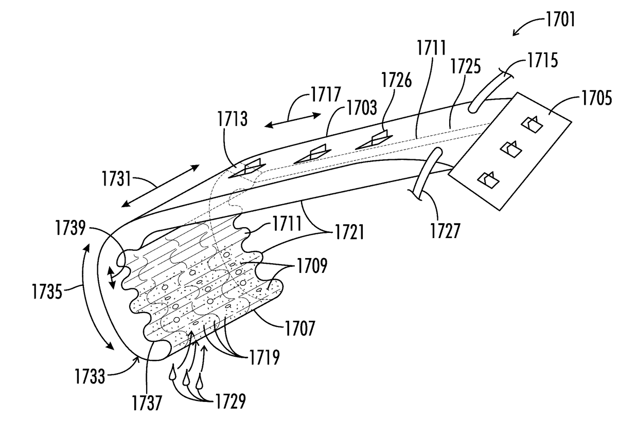
[0084]FIG. 12 is a perspective view of a hybrid rotus Type I retraction device according to a third embodiment of the invention. Device 1200 is comprised of rose texture side 1210 and lotus texture side 1212. A rose texture 1210 is characterized by the geometry of a water drop 1214 wherein drop 1214 takes on a spherical shape 1216 characteristic of a superhydrophobic surface. Drop 1214 is immobilized on the surface 1210 due to wicking geometry 1218. A lotus texture 1212 is characterized by the geometry of water drop 1220 wherein the shape is spherical with the absence of a wicking structure analogous to feature 1518. Drop 1220 resists adhesion to surface 1212, and readily rolls off the surface.

Corrugated Type II

[0085]FIG. 13 is a side view of a corrugated Type II retraction device according to a fourth embodiment of the invention. It should be understood a manually actuated Type I version is also possible. Device 1300 can be in two configurations 1310 and 1312. Configura...


PUM


Abstract

Retraction of one or more three-dimensional or planar amorphous objects is provided to gain access for a procedure where the retracted elements are easily damaged by application of normal forces. For example, a surgical instrument to provide access to an organ or tissue plane. Microtextured surfaces are provided that provide immobilization of amorphous objects, the immobilization of which is characterized by low normal forces and high shear or in plane forces. The retraction device is comprised of microstructured surfaces on one or more arms. Preferably these arms are soft and flexible to minimize damage to retracted objects. In some instances, these arms resemble and are used as a nonslip tape. Alternatively, parts or whole arms of the retraction device are rigid to provide a supportive aspect. These arms may be configured around a handle. Furthermore, the microtextured aspect may be further augmented with conventional gripping surfaces, such as a sticky surface, or a surface comprised of one or more hooks or barbs. The handle means may be distributed over the retraction device, for example, holes distributed along the arms through which anchoring means are tied. The retraction device is particularly well suited for grasping wet, oily, slimy or living surfaces by applying a small nondestructive normal force.

Description

RELATED APPLICATIONS[0001]This application claims the benefit of U.S. provisional application No. 62 / 237,448 filed on Oct. 5, 2015, the contents of which are hereby incorporated by reference in their entirety.TECHNICAL FIELD[0002]The present disclosure relates to surgical retractors comprising microtextured surfaces. The surgical retractors comprise a microtextured surface on one or more portions of the retractor, thereby advantageously providing immobilizing or positioning forces to a wet tissue surface while preventing or minimizing damage or trauma to the tissue.BACKGROUND[0003]There are many objects, natural and manmade, that are characterized by possessing a relatively durable surface enclosing delicate structures that would be adversely altered by a force applied normal to the durable surface and unaltered by a force applied tangent or in plane to the durable surface. Therefore, there is a need in the art for a retracting device that allows these objects to be immobilized, rel...

Claims


Application Information

Patent Timeline
Patent Type & Authority Applications(United States)
IPC IPC(8): A61B17/02
CPCA61B17/0218A61B2017/0225A61B2017/0243A61B17/02A61B2017/00858A61B2017/00938A61B2017/0096A61B2017/0237A61B2017/00557A61B2217/005A61B2017/00345
Inventor MILBOCKER, MICHAELBLUECHER, LUKAS
Owner BVW HLDG
Why Eureka
Try Eureka